24
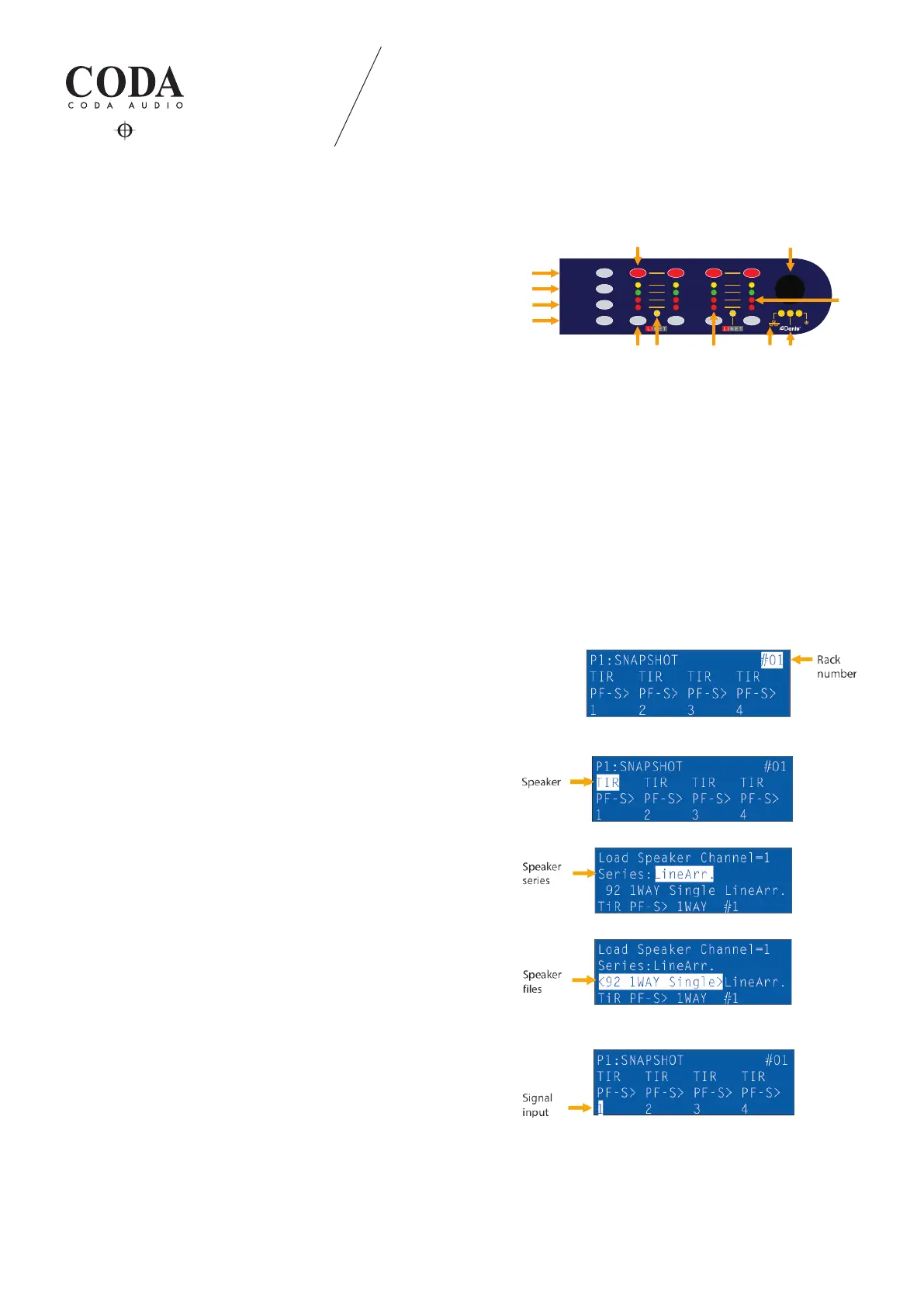
4.1 Screen user interface
Indication:
1. Channel mute buttons
2. Rotary encoder knob selects, changes and enters parameters
3. Press “ESC“ escape button anytime to deny selection and/or go
back to main operation page
4. “STORE“ snapshots 1-10
5. “UP“ skips operation pages up
6. “DOWN“ skips operation pages down
7. LiNET LED will indicate, if LiNET signal input signal is selected:
- LED on → LiNET audio input (clock present)
- LED o → Analog audio input selected
- LED ashes constant - - - → No LiNET audio input (clock missing)
- LED ashes with interval - o → Analog fallback enabled. Analog audio
input in use (clock present)
8. Channel selection buttons
9. Input/output signal and protection LEDs
10. Ethernet connection LED
11. Dante signal input LED (LINUS14D only)
12. Comparator LED for sensor controlled subs:
- LED on → Sensor loop is not closed
- LED o → Sensor loop is closed
4.1.1 Module number
Move the selection eld with the encoder knob to the module number
and push to enter selection.
Turn encoder knob to select a number from 1 to 250 and press to
conrm.
4.1.2. Speaker selection
Move the selection eld with the encoder knob to the desired
amplier channel.
Press encoder knob to enter speaker series selection.
Series selection: ALL, Line Array, APS Series, N-APS Series, HOPS Series,
Column Line Source, G-Series, D-Series, Subs, Monitors, Discontinued.
Press encoder knob to enter speaker le selection and move selection
eld to the next row.
Press encoder knob to conrm.
4.1.3 Input signal routing
Move the selection eld with the rotary encoder knob to the desired
amplier channel.
Select the input signal type and source (analog or digital):
- Input signal chart - analog inputs: A, B, C, D
- LINET (digital) inputs: 1, 2, 3, 4, 5, 6, 7, 8.
LINUS14/14D 4. OPERATION
4. OPERATION
LIMIT
SIGNAL
SENSOR
PROTECT
MUTE
SEL
ESC
UP
DOWN
1 2
3
4
STORE
3.
4.
5.
6.
1.
9.
7.
8.
2.
10.
11.
12.