TN910 Codan MT-3 and IFR COM-120 Test Procedures
MT-3 Radio Systems
TECHNICAL NOTES
TN910 Rev 5-0-0 May 14Page 4 of 16
© 2014 Codan Limited All rights reserved.
43 Erie Street
Victoria, B.C.
Canada V8V 1P8
Toll Free Canada & U.S.A.
Phone: 1-800-664-4066
Fax: 1-877-750-0004
International
Phone: 250-382-8268
Fax: 250-382-6139
Internet
Email: LMRsales@codanradio.com
Web: www.codanradio.com
System Regulator Testing
System Voltage Testing
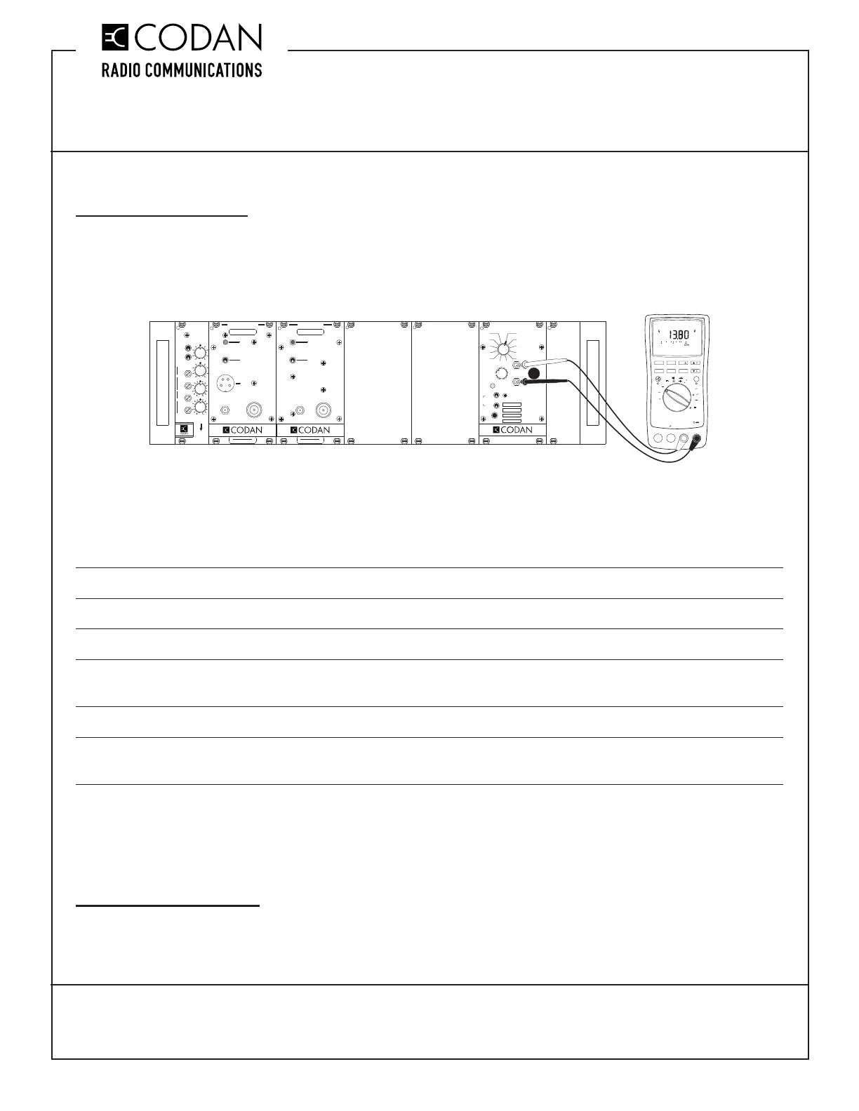
The fi rst stage of testing a Codan MT-4E radio system is to perform a basic system check on the supply and
regulated voltages. The System Regulator module is designed with a convenient and easy test point built in to the
front panel. This test point allows a technician access to the DC supply and regulated voltages. Simply connect
a standard Digital Volt Meter (DVM) to the METER jacks on the front panel of the System Regulator as shown in
Figure 1.
Figure 1: System Regulator Voltage Testing
The FUNCTION rotary switch on the front panel of the System Regulator will allow you to test various points in the
radio system. Following is a list of System Regulator rotary switch positions, the functions they measure and the
parameters measured:
1 Supply Voltage +10 Vdc to +17 Vdc (+13.8 Vdc nominal)
2 +9.5 Volts Regulated +9.5 Vdc (± 0.1 Vdc)
3 Rx A Audio Receiver A Audio (NOT Rx Balanced Output)
4 Rx A Carrier Strength 0 Vdc to +5.0 Vdc based on received signal strength
(0 Vdc is a low RF signal level, +5.0 Vdc is high)
5 Rx B Audio Receiver B Audio (NOT Rx Balanced Output)
6 Rx B Carrier Strength 0 Vdc to +5.0 Vdc based on received signal strength
(0 Vdc is a low RF signal level, +5.0 Vdc is high)
The standby current draw of the radio system should be measured for battery / solar powered systems. Connect
an ammeter to the power input line and measure the standby current draw and transmit current draw of the system.
The maximum standby and transmit current draw is dependant on the radio system (number and class of receivers,
transmitter output power, amplifi ers, auxiliary equipment, etc.).
Backwards Compatibility
The SM-3 System Regulator is a direct replacement for the SM-3 System Monitor, however, the rotary switch
positions for the front panel test points have been changed.
SQ . DI SAB LE
N
O
RMO
FF
RF NI
REFERENCE
INPUT
RECEIVER
FREQUENCY (MHz)
MADE IN CANADA
MODEL # CODE
TX
REFERENCE
INPUT
OFF
KEY TX
MIC
RF OUT
FREQUENCY (MHz)
NORM
TRANSMITTER
FREQUENCY (MHz)
MADE IN CANADA
MODEL # CODE
57
57
AUDIO
CONTROL
RX A
RX B
TX A
TX B
TX A
TX B
5
9
13
5
9
13
PULL DOWN
TO REMOVE
VOL
SYSTEM REGULATOR
METER
+
-
MADE IN CANADA
ON
OFF
SPKR
INT
EXT
EXT
SPKR
OFF
POWER
ON
2
1
5
4
3
67
8
11
10
9
FUNCTION
12
MIN MAXHOLD
REL
%
ms
Hz
RANGE
dB
dB
ac+dc
ac+dc
ac+dc
ac+dc
F
nS
mA
mA
A
mV
V
mV
V
OFF
C
A
A
A
A
mA
COM
V
TEMPERATURE
A
MIN MAXHOLD
REL
%
ms
Hz
RANGE
dB
dB
ac+dc
ac+dc
ac+dc
ac+dc
F
nS
mA
mA
A
mV
V
mV
V
OFF
C
A
A
A
A
mA
COM
V
TEMPERATURE
A
AutoHOLD
LOGGING
SAVECANCEL
FAST MN MX
SETUP
YES
NO
DIGITAL MULTIMETER
CLEAR MEM
VIEW
DC
This product has been discontinued and is no longer manufactured by Codan Radio Communications