9
WARNING
!
Connection of a 58 watt speaker to the siren amplier will cause the speaker to burn out, and will void the speaker
warranty!
WARNING
!
Any electronic device may create or be affected by electromagnetic interference. After installation of any electronic
device, operate all equipment simultaneously to insure that operation is free of interference.
WARNING
!
Utilizing non-factory specied screws and/or mounting brackets and/or the improper number of screws may result
in failure of the mounting system and severe damage to the vehicle as well as loss of warranty coverage on the
equipment.
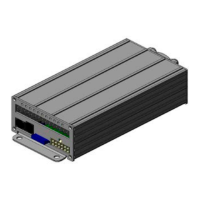
Amplier Power Distribution
The Level 1, 2, 3A and 3B outputs can supply a maximum of 15 Amps each or a combined total of 50 Amps. Each Level has a 20 Amp fuse installed
inside the Amplier. Fuses may be accessed through the panel on top of the Amplier.
The Auxiliary outputs A, B, C and D can supply a maximum of 5 amps each. Auxiliary outputs E, F, G and H can supply a maximum of 10 amps each.
The combined total for all Auxiliary outputs is 50 Amps. Auxiliary outputs A, B, C and D have 7.5 amp fuses and Auxiliary outputs E, F, G and H have
15 amp fuses. Fuses may be accessed through the panel on top of the Amplier.
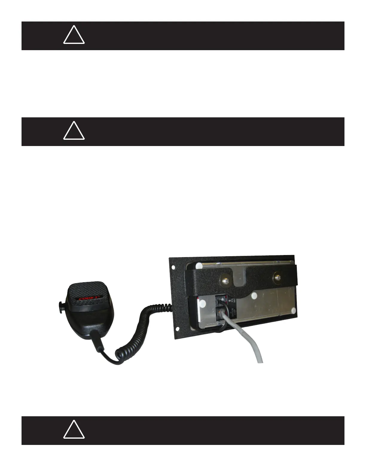
Control Head Connections
The connection from the Control Head to the remote Amplier is made using a standard CAT-5 cable (P/N T56649) connected to the port labeled
SIREN AMP on the back of the Control Head. This cable is found in the Harness & Cable Bag P/N T56641. See gure 5 below.
In addition, the microphone P/N T11856 connects to the Control Head port labeled PA MIC. The microphone also uses a Microphone Hanger Bracket
(P/N T00631) that mounts to the dash of the vehicle.
Figure 5