4
ENGLISH
GENERAL
Read carefully the instructions before installing this unit.
Verify the technical characteristics of the motor in order to
assure the compatibility with the device.
DESCRIPTION
• EPR - Electronic Pressure Regulator -
Is an electronic drive for single-phase pumps up to 2,2 kW
(1~115-230V) with an innovative system of pressure reduc-
tion/regulation in order to mantain an steady outlet pres-
sure. Therefore, in addition to the typical features of tra-
ditional electronic pump controllers: integrated non-return
-
ge, indicator led-lights, dry-run protection, automatic res-
tore system (ART), ... it is adjusted and stabilized the output
pressure, avoiding overloads and water hammer, ultimately,
improving the comfort and durability of the installation.
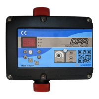
• DPR - Digital Pressure Regulator -
Evolutes from EPR, adding to its features a digital display
with instataneous indication of current consumption and
outlet pressure since it houses current and pressure transdu-
cers inside. This device allows disassociating the regulation
of the outlet pressure from the cut-in pressure to improve
the elasticity of the system’s hydraulic reserve, favoring the
prolongation of inactive pauses and, consequently, redu-
cing the number of starts of the electric pump. This inde-
pendence from pressure regulation also allows operation
(ON) and the outlet pressure (OUT). It also integrates alarm
and function registers, as well as the possibility of adjusting
multiple operating parameters such as automatic reset sys-
OPERATING CHARACTERISTICS
EPR DPR
Starting pressure Depends on the
adjusted outlet
pressure. Table 1.
Adjustable from
0,5bar to 5,5bar.
Table 2.
Outlet pressure Adjustable from
2,5 bar to 6 bar
by the rear allen
screw. Figure 1
and 2.
Adjustable from
2,5 bar to 6 bar
by the rear allen
screw. Figure 1
and 2.
Outlet pressure
reading
Manometer Digital
Dry-running pro-
tection
Yes Yes
Overcurrent pro-
tection
No Yes
ART* Fuction Yes Yes
Manual start
push-button
Yes Yes
Control panel LED indicator
lights and ENTER
push button
3-digit display,
LED indicator
lights and 4 push
buttons (up and
down arrows,
amps and enter)
APR function* Yes Yes
No Yes
Stand-by mode No Yes
*ART FUNCTION (Automatic Reset Test)
When the device has stopped the pump by the interven-
tion of the dry-running protection system the ART tries,
after 5 minutes, to re-start the pump in order to restore the
water supply.
every 30 minutes.
In the DPR, this function can be activated in the ADVAN-
CED MENU. It can also be set the number of attempts (1-
48) and the span of the attempt (10-40 seconds).
*APR FUNCTION (Anti-blocking Periodic Routine)
After 72 hours without operation the pump is automatically
started for 10 seconds in order to avoid rotor locking. In
the DPR the display will show the message “APr” while the
pump is operating. In the EPR the pump LED will be on
during this operation.
TECHNICAL CHARACTERISTICS
• Rated motor power: 0,37-2,2KW
• Power supply: ~1 x 110-230Vac
• Frequency: 50/60Hz
•
• Protection degree: IP65*
• Maximum water temperature: 50ºC
• Maximum environment temperature: 60ºC
• Outlet pressure: (±0.5 bar) 2,5-6 bar
• Starting pressure range:
• DPR: 0,5 - 5,5 bar (factory setting 1,5 bar)
• EPR: 1,0 - 4,5 bar. Table 1.
• Maximum operating pressure: 10 bar
• Hydraulic connection (types): G 1” M
NPT 1” M
• Net weight (without cables): 2 kg
*Plugs and sockets built into the wiring of the device
could modify the declared IP rating.
HIDRAULIC INSTALLATION (diagram A)
Before proceeding with hydraulic connection it is
essential to prime the pump correctly. DPR or EPR
must be installed in a vertical position (arrows in upward
position), thus connecting the inlet opening directly to the
pump outlet; and the outlet to the network. The following
link for network protection, protecting the set from possible
isolation of the pump from the net, a tap at the same level
of the unit. See diagram A.
ELECTRIC CONNECTION (diagram B)
The electric connection must be performed by qua-
each country. Before doing manipulations inside the device,
it must be disconnected from the electric supply.
Wrong connection could spoil the electronic circuit.
The manufacturer declines all responsability in dama-
ges caused by wrong connections.
Check if power supply is beetween 110-230V.
If you have purchased the unit without cables follow dia-
gram B. EPR and DPR devices have the same electric wiring
diagram.
• Use cables type H07RN-F 3G1 or 3G1,5 with section
enough to the power installed.
• Do the pump connection U, V and .
• Do the power supply connection L, N and .
• The earth conductor must be longer than the others. It
and the last one to be disconnected during the dis-
mantling.
The earth conductors connections are compulsory!

 Loading...