INSTATTATION
INSTRUCTIONS
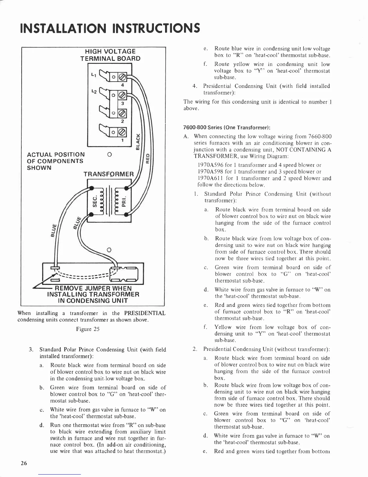
HIGH
VOLTAGE
TERMINAL BOARD
Y
o
o
ACTUAL
POSITION
OF COMPONENTS
SHOWN
TRANSFORMER
REMOVE
JUMPER
WHEN
I NSTAL
LI NG TRANSFO
RMER
IN
CONDENSING UNIT
When installing a transformer in the PRESIDENTIAL
condensing units
connect
transformer
as shown above.
Figure 25
3.
Standard
Polar Prince
Condensing Unit
(with
field
installed transformer) :
Route
black wire
from
terminal board on side
of blower
control box to wire nut on black wire
in the
condensing unit.low voltage box.
Green wire from terminal board on
side
of
blower control
box
to
"G"
on
'heat-cool'ther-
mostat
sub-base.
White wire
from
gas
valve in furnace to
"W"
on
the'heat+ool' thermostat
sub-base.
Run
one
thermostat
wire from "R"
on
sub-base
to
black wire extending from auxiliary limit
switch
in furnace and wire nut together in fur-
nace
control box.
(In
add-on air
conditioning,
use wire that
was attached
to
heat thermostat.)
a.
b.
d.
e.
Route
blue wire in condensing unit low voltage
box to
"R"
on
'heat<ool'thermostat
sub-base.
f.
Route
yellow
wire in
condensing unit low
voltage
box to "Y' on
'heat-cool'
thermostat
sub-base.
4. Presidential
Condensing
Unit
(with
field installed
transformer):
The
wiring for
this
condensing unit is identical to number
above.
7600-800
Series
(One
Transformer):
A. When
connecting
the
low
voltage wiring
from 7660-800
series
furnaces
with
an
air conditioning
blower in
con-
junction
with
a condensing
unit, NOT CONTAINING A
TRANSFORMER, use
Wiring Diagram:
1910A596 for
I transformer and 4 speed blower or
1970A598 for
I transformer
and 3 speed blower
or
1910A6l
I for
I transformer
and
2
speed
blower
and
follow
the directions
below.
1.
Standard
Polar
Prince
Condensing
Unit
(without
transformer):
a.
Route black wire from
terminal board
on
side
of
blower control box to wire nut on black wire
hanging from
the side of the
furnace
control
box.
b.
Route black wire from low voltage box of
con-
densing unit to wire nut on black wire
hanging
from
side
of furnace
control box. There should
now be three wires tied together at this
point.
c.
Green
wire
lrom terminal board
on
side of
blower control box
to
"G"
on
'heat-cool'
thermostat
sub-base.
d. White wire
from
gas
valve in
furnace to
"W"
on
the'heat-cool'
thermostat sub-base.
e.
Red and
green
wires
tied together from bottom
of furnace
control
box to
"R"
on
'heat-cool'
thermostat
sub-base.
f.
Yellow
wire from low
voltage
box of
con-
densing unit
to
"Y"
on
'heat-cool'
thermostat
sub-base.
2. Presidential
Condensing Unit
(without
transformer):
a.
Route black wire from terminal board on
side
of
blower
control box
to
wire
nut on
black wire
hanging from
the side of the
furnace
control
box.
b.
Route black
wire
from
low voltage
box of
con-
densing
unit to wire nut on black wire hanging
from
side of furnace
control
box. There should
now
be
three
wires tied together at this
point.
c. Green wire from terminal board on
side
of
blower
control box to
"G"
on
'heat-cool'
thermostat
sub-base.
d.
White wire from
gas
valve in
furnace to
"W"
on
the'heat-cool'
thermostat sub-base.
26
e.
Red and
green
wires tied together
from
bottonr