4
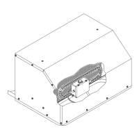
5. CEILING PLENUM INSTALLATION REQUIREMENT
1. The ceiling plenum must be installed under the roof
opening.
The ceiling plenum bolts below the roof top unit.
Compression of the framed ceiling cavity between the
roof top unit and the ceiling plenum is what holds both
components in place.
2. Ceiling cavity depth (the measurement from the ceiling to
the roof – maximum 6”).
3. The 115 VAC service for the roof top unit must be routed
into the ceiling plenum. To prevent wire pinching and to
promote ease of installation, allowances must be made for
routing the 115 VAC supply wiring into the front of the
roof opening.
4. The wirebox has a 9 pin receptacle extending from the
front. This mates with the roof unit 115 volt electrical
conduit. When making this connection, verify that the
plugs are properly aligned and have snapped together
securely.
5. The wirebox for the heat/cool units will have a two pin
receptacle which mates with the umbilical plug from the
heater assembly.
6. LOW VOLTAGE CONTROL WIRING (WALL
THERMOSTAT)
A. A low voltage terminal strip on the front of the box
connects to the low voltage control wires. The wires
attach by 1/4" quick connects.
B. The low voltage control wiring must be run from the
wall thermostat mounting location to the wirebox low
voltage terminals. To prevent wire pinching and to
promote ease of installation, allowances must be
made for routing the low voltage wiring into the front
of the opening.
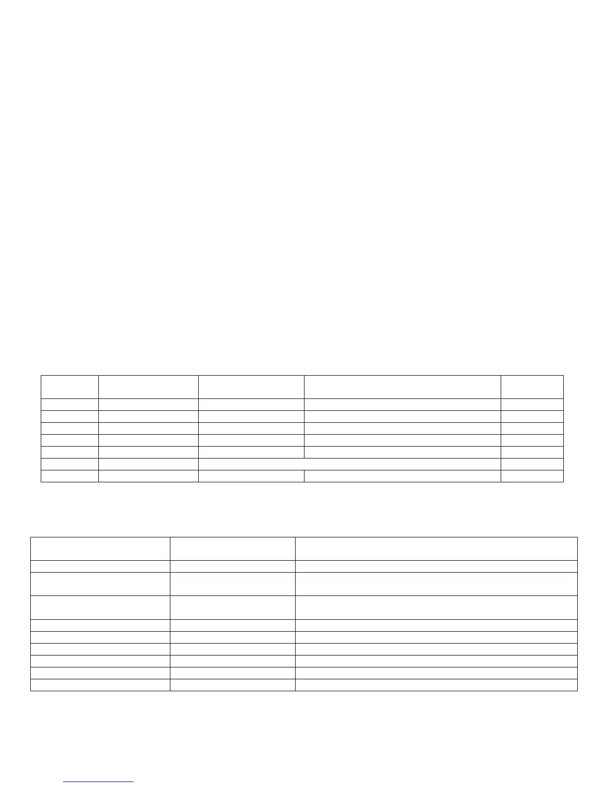
Standard Control Box
Zone Control Box
Plenum Terminal
Designation
Thermostat Wire
Connection
Function of Low Voltage Terminal Extending From Ceiling
Plenum
R+ Red Provides +12 VDC to upper unit control box
Cool Shed
(2 Terminals)
White
Jumper Wire
Removing jumper wire will allow system to be connected to N.C.
contacts of a load shed system
Heat Shed
(2 Terminals)
White
Jumper Wire
Removing jumper wire will allow system to be connected to N.C.
contacts of a load shed system
Room (2 Terminals) Any The remote room temperature sensor attaches here*
Freeze (2 Terminals) White Freeze sensor attaches here
Gen Any Allows system to connect to an automatic start generator system
B- Blue Provides -12 VDC to upper unit control box
Sig 1 Purple Communication line between upper unit control box and thermostat
Sig 2 Black Communication line between upper unit control box and thermostat
* Zone 1 has option of using thermostat as room sensor
Cool Only
Boxes
Plenum Terminal
Designation
Thermostat Wire
Connection
Function of Low Voltage Terminal
Extending From Ceiling Plenum
Heat Ready
Boxes
Yes B BLUE Completes -12 VDC circuit for all relays Yes
Yes Y YELLOW Energizes coil on Compressor Relay Yes
Yes GH GREEN Energizes coil on High Fan Relay Yes
Yes GL GRAY Energizes coil on Low Fan Relay Yes
Yes FREEZE WHITE Evaporator Freeze Sensor Connections Yes
Yes FREEZE
No W WHITE Energizes coil on Heat Relay Yes
 Loading...