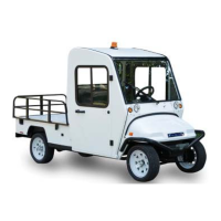
G
E
I
F
A
H
D
C
B
K
J
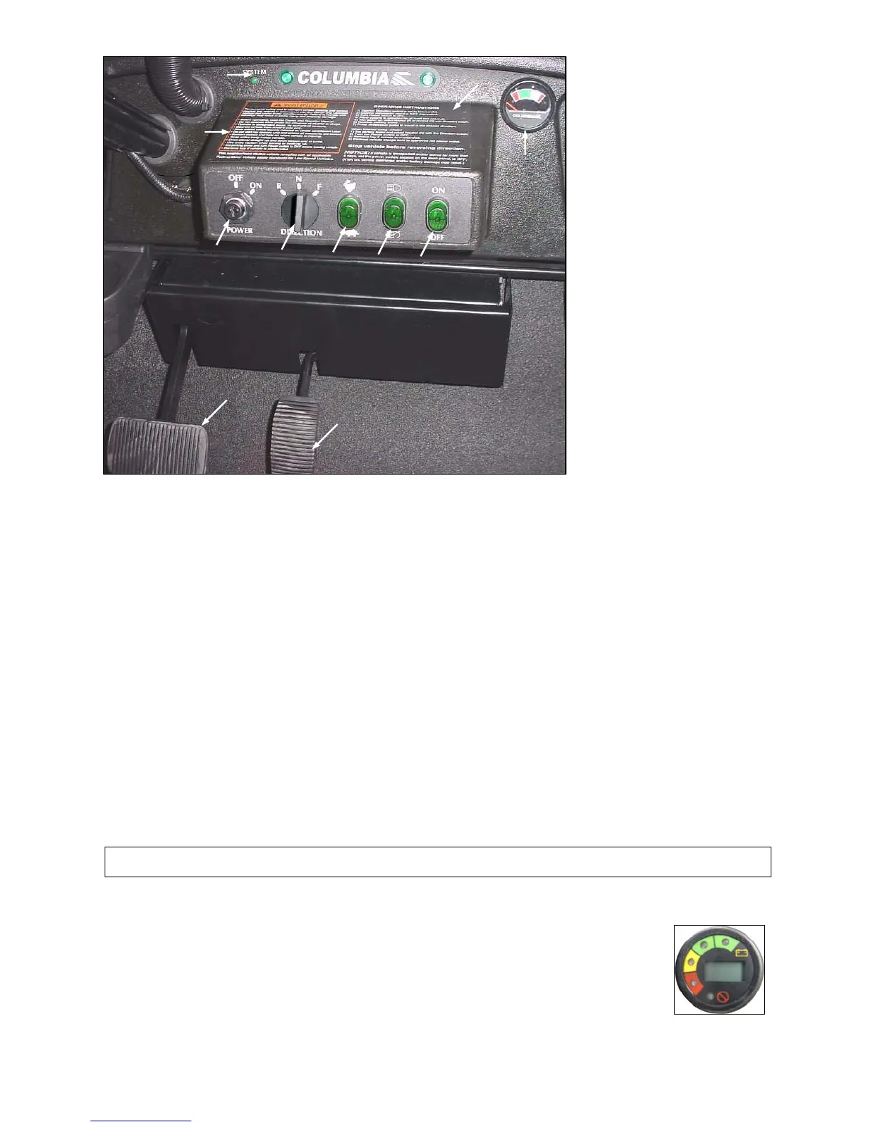
Figure 3.3.1
3.3.4 LIGHT SWITCH – Figure 3.3.1 Arrow D
The light switch is a two-position switch. Move switch up to activate headlights and taillights, down to turn off.
3.3.5 WINDSHIELD WIPER – Figure 3.3.1 Arrow E
If equipped, the windshield wiper switch (E) is a two-position toggle switch. Move switch up to activate wiper and
down to turn off.
3.3.6 BATTERY STATE OF CHARGE METER – Figure 3.3.1 Arrow F
Used only with DC Drive vehicles. This meter will display the battery state of charge. As shown, it is an analog gauge
meter with an indicating needle and a colored background. It is a continuously reading meter. At rest with fully
charged batteries the meter should read in the right white region.
When accelerating quickly, the needle will move to the left green region near the very far left red region. This is
normal. If the needle continues past the green region into the very far left red region, it indicates that the batteries are
80% discharged or basically empty (only 20% charge remaining). Recharge as soon as possible to avoid a shut-down
of the vehicle.
When decreasing speed, the needle will move to the right as electrical energy is being “regenerated” back into the
batteries.
NOTICE: At 80% discharge, you must immediately charge batteries or vehicle operation will cease and
permanent battery damage could occur.
3.3.6A MULTI-FUNCTIONAL DISPLAY INDICATOR – Figure 3.3.2
For AC Drive vehicle this Multi-functional Display Indicator will replace the Battery State of Charge
Meter and the System Status Light. This meter will display the battery state of charge, an hour
meter and the controller status. With fully charged batteries, the uppermost green LED is lit. A lit
lower red LED indicates discharged batteries. The hour meter is an alpha-numeric liquid crystal
display in the center of the MDI showing the hours worked.
If there is a control
ler error the hours worked will be replaced with a flashing error code. It is
important to note the error code. It will aid a technician in corrective actions.
Figure 3.3.2
2012 Summit
3-5