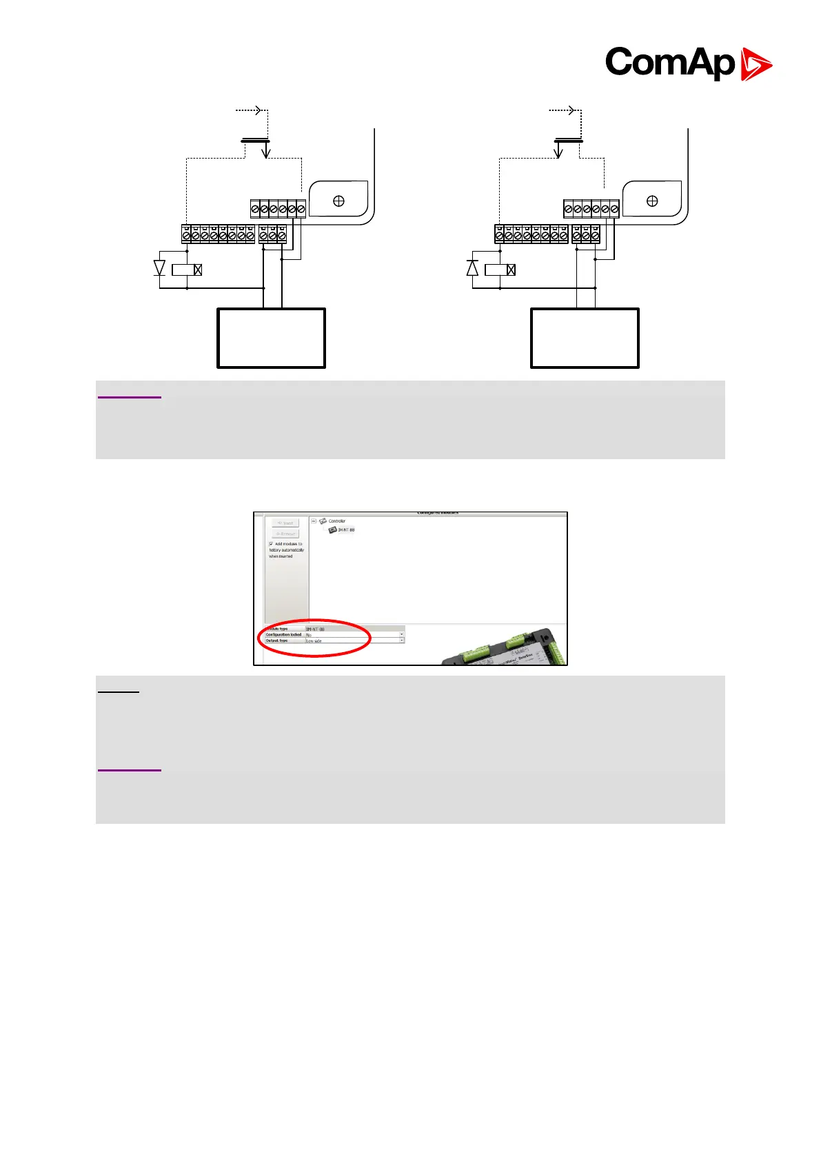
CAUTION!
Both power supply sockets for binary outputs need to be connected to ensure proper function
of binary outputs.
Never use DC relays without protection diods!
Low side or High side function of binary outputs can be chosen in configuration tool GenConfig
in Modules tab. This configuration is used for all binary inputs available on the controller.
NOTE:
Every group of outputs (i.e. 1..8 and 9..12) can provide steady current of up to 2A. Every
single binary output can provide up to 0.5A of steady current unless the total current of group
of outputs does not exceed 2A.
CAUTION!
Both “+” and “-“ terminals on the IS-NTC-BB, IG-NT-BB, IG-NTC-BB, IM-NT-BB and IM-NTC-
BB need to be connected at all times to ensure the proper function of Binary Ouptuts 9 to
12(16)!

 Loading...