Do you have a question about the ComAp InteliATS PWR and is the answer not in the manual?
Explains the meaning of HINT, NOTE, CAUTION, and WARNING paragraphs.
States compliance with EC directives for safety and EMC.
Outlines the manual's scope and intended audience.
Details compatibility between software and hardware versions.
Explains the automatic transfer switch controller's function and features.
Lists the included accessories and their obligatory/optional status.
Details the RS232 module for computer or Modbus connection.
Describes the dual port RS232 and RS485 communication module.
Explains the USB plug-in card for InteliATSNT communication.
Covers the Ethernet/Internet communication module.
Details the GSM/GPRS modem for remote communication.
Describes the remote signaling and control software.
Details the plug-in card for driving VDO style gauges.
Explains the module for accommodating binary inputs or outputs.
Describes the module for connecting to the internet or LAN.
Provides instructions for programming the controller.
Explains the two interchangeable user interface modes: USER and ENGINEER.
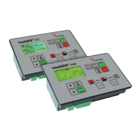
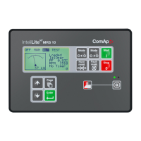
Illustrates the IA-NT PWR terminals and front panel layout.
Provides physical dimensions and mounting cutout information.
Shows the recommended wiring connections for the IA-NT PWR.
Describes the Auto Mains Failure application with two breakers.
Details the AMF application with a two-position ATS.
Provides general installation guidelines and power supply requirements.
Explains current measurement setup and transformer usage.
Details voltage measurement and connection types.
Describes the function and limitations of binary inputs.
Details the function and limitations of binary outputs.
Explains RS485 connection requirements and recommendations.
Covers password protection and basic controller settings.
Details generator connection types and changeover transition modes.
Covers controller address, COM1/COM2 modes, and Modbus speed.
Details IP address, Netmask, Gateway, and DHCP settings.
Covers AirGate service, SMTP server, and email configuration.
Defines engine start, cooling, and maximum start delay times.
Enables/disables generator voltage and frequency protections.
Details overload and short circuit protection parameters.
Configures behavior after returning from island to mains operation.
Defines delays for engine start and breaker transfer.
Sets voltage/frequency windows and synchronization timeout.
Covers time stamping, summer time, date, and time adjustment.
Details available functions for Timer1 and Timer2.
Configures sending SMS and email alarms remotely.
Explains the controller's OFF, MAN, AUT, and TEST operating modes.
Details manual operation of the engine and breakers.
Describes automatic mains failure and transfer sequences.
Explains controller behavior and options in TEST mode.
Illustrates timing relations for breaker operations.
Provides a simplified flowchart of the AMF sequence.
Explains how source health is evaluated (inputs, values, or both).
Describes available alarm types: Warning, Trip, and Mains failure.
Details the controller's electric state machine and possible events.
Explains how the history file stores important events.
Allows selection between USER and ENGINEER interfaces.
Details the LiteEdit software for PC connection and control.
Explains how to connect the controller via modem.
Describes connecting via Ethernet, IB-Lite, or IL-NT-GPRS.
Guides on accessing the controller via a web browser with IB-Lite.
Lists diagnostic codes for IL-NT-GPRS and AirGate connections.
Details the Modbus communication protocol and its objects.
Provides instructions for replacing the internal backup battery.
Summarizes available inputs and outputs per model.
Details voltage supply, consumption, and drop-out tolerance.
Specifies the physical dimensions and weight of the controller.
Provides electrical specifications for mains and generator.
Lists specifications for optional communication and extension cards.
| Power Supply | 8-36 V DC |
|---|---|
| Operating Temperature | -20°C to +70°C |
| Protection Class | IP20 |
| Communication Ports | RS485 |
| Storage Temperature | -30°C to +80°C |
| Humidity | 95% non-condensing |
| Supported Protocols | Modbus RTU |
| Display | Graphical LCD |


 Loading...