EasyManua.ls Logo

ComAp InteliATS NT PWR User Manual

ComAp InteliATS NT PWR
69 pages
To Next Page IconTo Next Page
Page #1 background imageLoading...
Page #1 background image
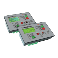
InteliATS
NT
®
Automatic Transfer Switch Controller
IA-NT PWR unit
SW version 1.2, January 2010
Reference Guide
January 2010
Copyright © 2010 ComAp s.r.o.
Written by Vlastimil Vostřák
Prague, Czech Republic
ComAp, spol. s r.o.
Kundratka 2359/17, 180 00 Praha 8, Czech Republic
Tel: +420 246 012 111, Fax: +420 246 316 647
E-mail: info@comap.cz, www.comap.cz

Table of Contents

Question and Answer IconNeed help?

Do you have a question about the ComAp InteliATS NT PWR and is the answer not in the manual?

ComAp InteliATS NT PWR Specifications

General IconGeneral
Operating Temperature-20 to +70 °C
Communication PortsRS232, RS485, CAN
Inputs8 binary inputs
Outputs6 relay outputs
ProtectionIP20
Storage Temperature-30 to +80 °C
Humidity95% non-condensing
CertificationsCE, UL
Power Supply Voltage8-36 V DC
DisplayLCD
Weight0.5 kg
Relay Outputs6 configurable relays

Summary

General Guidelines

Safety Warnings and Notes

Covers critical warnings on compatibility and remote control safety.

Controller Configuration

User Interface

Terminals and Front Panel

IA-NT PWR Terminal Layout

Illustrates the IA-NT PWR terminals and front panel layout.

Wiring and Connections

IA-NT PWR Wiring Diagram and Breaker Interlocking

Provides wiring diagram and recommends breaker interlocking.

Typical Applications

AMF with Two Breakers (MCB/GCB) and Test on Load

Details AMF applications with two breakers and test on load functionality.

ATS Applications

AMF with Two-Position and Three-Position ATS

Details AMF applications with two and three-position ATS, including specifications.

Advanced AMF Scenarios

Manual Transfer and No Battery Operation

Covers AMF with manual transfer and operation without battery, with requirements.

Getting Started with Installation

Installation Guidelines, Power Supply, and Grounding

Covers general installation, power supply, grounding, and voltage dip considerations.

Application Measurement and Grounding

Three-Phase Measurement and Grounding

Details grounding, current, and voltage measurements for three-phase applications.

Single-Phase Application Configuration

Input/Output Diagrams

Input and Output Configuration Options

Detailed Binary Inputs

Default Inputs, List, and Key Functions

Lists default binary inputs and explains functions like Rem Start/Stop and Access Lock.

Detailed Binary Outputs

Controller Setpoints

Engine and AMF Parameters

Generator Protection Settings

Short Circuit and Overcurrent Protection

Configures protection enable, short circuit, and IDMT overcurrent settings.

AMF Settings

SMS/E-Mail Alarm Messaging

Remote Alarm Messaging Setup

Configures sending SMS/emails for alarms, including modem requirements.

Alarm Message Configuration and Target Addresses

Configures alarm message types and target phone/email addresses.

Function Description

Circuit Breaker Timing Diagrams

Mains Fail, Gen-set Start, and Mains Return Timing

Timing diagrams for mains fail, gen-set start, and mains return events.

GCB and MCB Interaction Timing in AUTO and TEST Modes

Timing diagrams for GCB and MCB interaction in AUTO and TEST modes.

Alarm Management

Alarm Categories, Descriptions, and Reasons

Explains alarm types (warning, trip, mains failure) and refers to reason lists.

AMF Time Charts

Gen-set OK and Not Started Properly Sequences

Time charts illustrating AMF sequences for different gen-set scenarios.

Voltage Phase Sequence Detection

Phase Sequence, GCB/MCB Fail Detection, and Resolution

Explains phase sequence detection, GCB/MCB fail detection, and resolution methods.

Remote Control and Data Logging

Communication Object Mapping

Remote Communication Methods

IL-NT-RD Wiring and Connection

Maintenance Procedures

Backup Battery Replacement

Step-by-step instructions for replacing the internal backup battery.

Related product manuals