Do you have a question about the ComAp InteliATS NT STD and is the answer not in the manual?
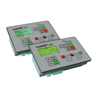
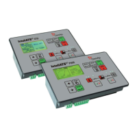
Describes the InteliATSNT as a comprehensive Automatic Transfer Switch controller.
Details the RS232 communication module for computer connectivity.
Describes the dual port module for RS232 and RS485 communication.
Details the USB communication module for computer connectivity.
Explains the remote display software for monitoring and control.
Describes the module for Ethernet/Internet communication.
Details the extension module for adding binary inputs/outputs.
Provides instructions and diagrams for mounting the controller onto a switchboard door.
Shows the complete wiring diagram for the IA-NT STD controller.
Describes the Auto Mains Failure application using MCB and GCB.
Details the Auto Mains Failure application with a two-position ATS.
Explains the Auto Mains Failure application using a three-position ATS.
Covers AMF with manual transfer and neutral control via three-position ATS.
Describes the AMF application without a controller battery supply.
Explains cascading applications for splitting load across multiple sections.
Provides general installation guidelines including wiring and power supply.
Details voltage measurement and wiring for three-phase applications.
Provides a simplified diagram of the AMF transition states.
Provides an overview table of the controller's inputs and outputs.
Specifies the power supply voltage, consumption, and drop-out tolerance.
Specifies nominal frequency, voltage inputs, and resistance.
| Model | InteliATS NT STD |
|---|---|
| Type | Automatic Transfer Switch Controller |
| Operating Temperature | -20 to +70°C |
| Storage Temperature | -30 to +80°C |
| Inputs | 8 binary inputs |
| Protection Class | IP20 |
| Certifications | CE, UL |
| Humidity | 95% non-condensing |
| Communication | RS485, Modbus |
| Display | LCD with backlight |
| Protection | Overvoltage, Undervoltage |
| Weight | 0.5 kg |


 Loading...