Do you have a question about the ComAp InteliLite NT AMF Series and is the answer not in the manual?
Explains the purpose and audience of the manual.
Highlights critical safety warnings and precautions for operation.
Defines text formatting used in the manual for buttons, setpoints, etc.
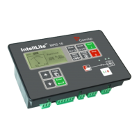
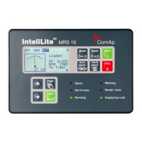
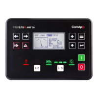
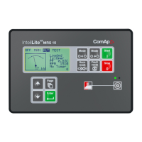
Provides a general overview of the InteliLiteNT AMF20/25 controller and its features.
Lists the accessories included in the product package.
Describes the IL-NT RS232 plug-in card for communication.
Details the IL-NT AOUT8 card for driving industrial gauges.
Explains the software for remote monitoring and control of the controller.
Describes the IGL-RA15 remote annunciator connectable via CAN bus.
Illustrates the controller's terminal connections and front panel layout.
Shows the wiring diagram for Automatic Mains Failure (AMF) applications.
Explains wiring for standby applications using contactors.
Describes wiring for ATS with three stable positions.
Covers essential points for proper installation and wiring.
Specifies voltage, current, and connection requirements for the power supply.
Details the connection and function of the magnetic pick-up for speed sensing.
Explains how to connect for accurate current measurement using CTs.
Illustrates voltage measurement connections for three-phase and single-phase systems.
Notes on configuring the controller for single-phase applications.
Explains jumper configuration for analog inputs and reading from ECU.
Details available analog input types and their configurable parameters.
Illustrates the wiring for binary inputs.
Shows the wiring for binary outputs.
Lists the default functions assigned to binary inputs.
Describes available binary input configurations like Not Used and Alarm.
Lists the default functions assigned to binary outputs.
Details functions of binary outputs like Starter, Fuel Solenoid, Stop Solenoid.
Explains jumper configuration for analog inputs and reading from ECU.
Describes Oil Pressure, Water Temp, and Fuel Level analog inputs.
Covers setting and changing the controller password for protected setpoints.
Configuration of essential parameters like Gen-set Name, Power, Current, CT Ratio.
Sets the interval for periodic history records.
Configures automatic switching between summer and winter time.
Configuration for warning and shutdown alarms on IOM/PTM analog inputs.
Setting up SMS and email notifications for alarms.
Explains how to correct analog input measurement errors via calibration.
Lists available resistive sensor curves and their min/max values.
Describes the controller's behavior when in OFF mode.
Explains manual mode operation, including start, stop, and breaker control.
Outlines the simplified start-stop sequences for MAN and AUT modes.
Details automatic mains failure operation and sequence.
Explains how the controller operates in test mode.
Describes the different alarm categories and their indicators.
Explains how mains failure is detected and the resulting actions.
Visualizes the timing of various events and protections.
How the controller detects and alarms on incorrect voltage phase connections.
Explains how sensor failures are detected and displayed.
How circuit breaker failures are detected based on feedback.
Defines the various states of the engine and controller operation.
Describes the controller's electrical states related to mains and breakers.
Comprehensive list of events, their protection types, and descriptions.
Instructions for connecting to a PC using LiteEdit for monitoring and configuration.
Details the Modbus protocol functions and specifications for serial communication.
Setup for ISDN and GSM modems for remote communication.
Guidance on configuring the SIM card for GSM modem use.
Details voltage, consumption, and voltage drop-out characteristics.
Environmental and operational specifications like temperature, humidity, and certifications.
Physical dimensions, weight, and generator/mains electrical parameters.
Technical details for binary I/O, analog inputs, and their ranges.
Specifications for speed pick-up sensors and the D+ function.
Details on CAN bus parameters, cable types, and recommended cables.
| Model | InteliLite NT AMF Series |
|---|---|
| Automatic Mains Failure (AMF) | Yes |
| Communication Ports | RS232, RS485, USB, Ethernet |
| Operating Temperature | +70 °C |
| Protocols | Modbus |
| Protection | Over/under voltage, over/under frequency, phase sequence |
| Event Log | Yes |
| Remote Monitoring | Yes |


 Loading...