InteliLite
NT
– AMF20/25, SW version 1.2, ©ComAp – March 2008 21
IL-NT-AMF-Reference Guide1.2.pdf
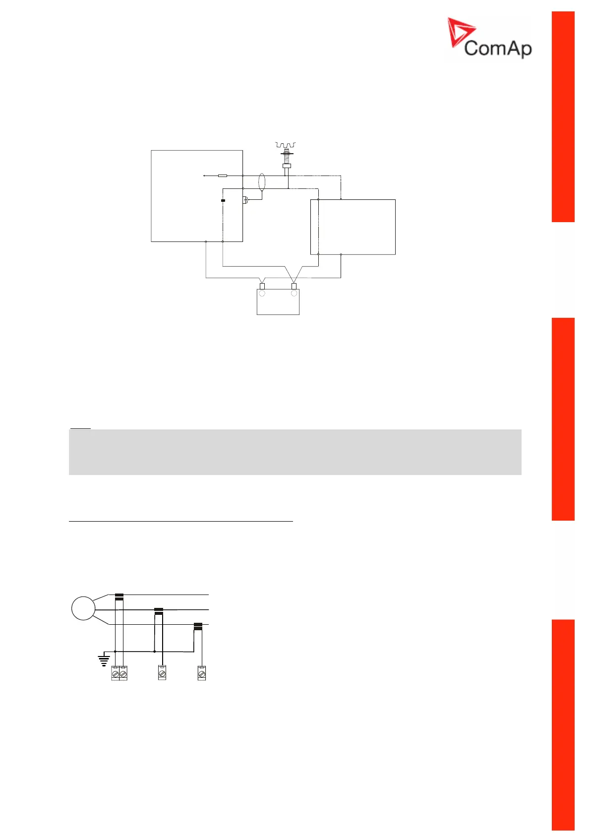
Magnetic pick-up
To ensure proper function:
Use a shielded cable
+
Battery
-
iL
GAC
Speed Control Unit
ESD 5500
MAGNETIC
PICK-UP
C
D
a
b
Signal
Signal
+
+
-
-
Power
Supply
Power
Supply
Be aware of interference signal from Speed governor when one speed pick-up is used.
If engine will not start:
- Check ground connection from pick-up to controllers, eventually disconnect ground connection
to one of them
- Galvanically separate InteliLite RPM input using ComAp separation transformer RPM-ISO
(1:1)
- Use separate pick-up for Speed governor and InteliLite
NT
Hint
:
In some cases the controller will measure a RPM value even though the gen-set is not running:
RPM is measured from the generator voltage (Gear Teeth = 0)
IL-NT is measuring some voltage value on input terminals due to open fusing.
If RPM > 0 the controller will be put into a Not ready state and the engine will not be allowed to start.
Current measurement
To ensure proper function
Use cables of 2,5mm
2
Use transformers to 5A
Connect CT according to following drawings
L1
L2
L3
N
G
COM L1l
K L
k l
L2l
K L
k l
L3l
K L
k l