InteliLite
NT
– AMF20/25, SW version 1.2, ©ComAp – March 2008 61
IL-NT-AMF-Reference Guide1.2.pdf
Sensor Specification
Background of the sensor calibration
To correct measuring error of each analog input (pressure, temperature, level) calibrating constants
within 10 % of measure range should be set. Two calibrating constants are set in physical units - bar,
o
C, % .Calibration is made by adding the value of setpoint AIxCalibration directly to the calculated
value at analog input.
Hint
:
The calibration must be done at the operational point of the analog input (e.g. 80°C, 4.0Bar etc..)
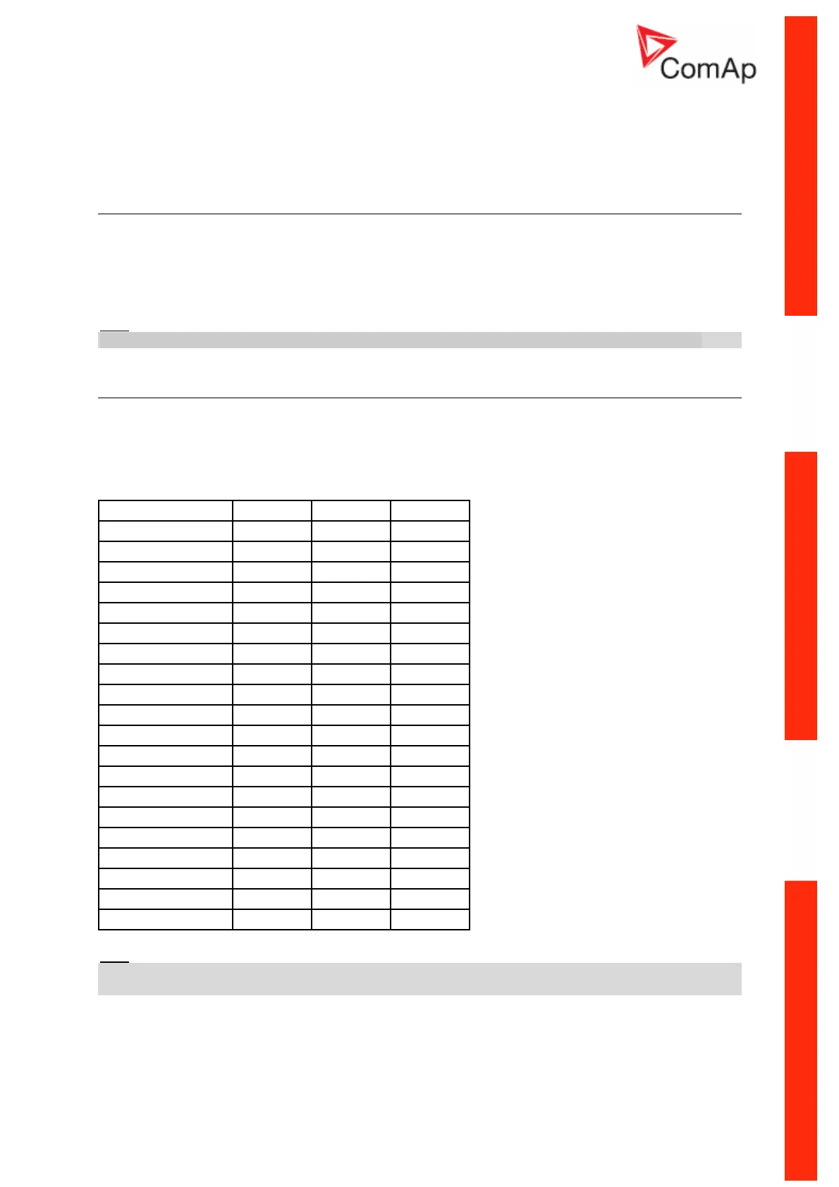
Default sensor curves
There are 20 resistive curves available. The following table provides information on
minimum/maximum values of respective sensors. Actual values especially of temperature curves may
differ. Meaning is to prolong curve to the lower temperature values, so the cold engine will not raise
alarm fail sensor.
Curve Min Value Max Value Unit
Datcon 5 Bar 0 5 Bar
Datcon 7 Bar 0 7 Bar
Datcon 10 Bar 0 10 Bar
Datcon 80 Psi 0 80 Psi
Datcon 100 Psi 0 100 Psi
Datcon 150 Psi 0 150 Psi
Datcon Low °C 25 150 °C
Datcon High °C 25 160 °C
Datcon Low °F 80 300 °F
Datcon High °F 80 320 °F
Datcon Fuel % 0 100 %
VDO 5 Bar 0 5 Bar
VDO 10 Bar 0 10 Bar
VDO 72 Psi 0 72 Psi
VDO 145 Psi 0 145 Psi
VDO 40-120 °C 40 120 °C
VDO 50-150 °C 50 150 °C
VDO 100-250 °F 100 250 °F
VDO 120-300°F 120 300 °F
VDO Fuel % 0 100 %
Hint:
When measured value is 6% out of range the Sensor fail FLS is detected. You can find detail
information on sensores in LiteEditu Reference Guide.