InteliLite
NT
– AMF20/25, SW version 1.2, ©ComAp – March 2008 27
IL-NT-AMF-Reference Guide1.2.pdf
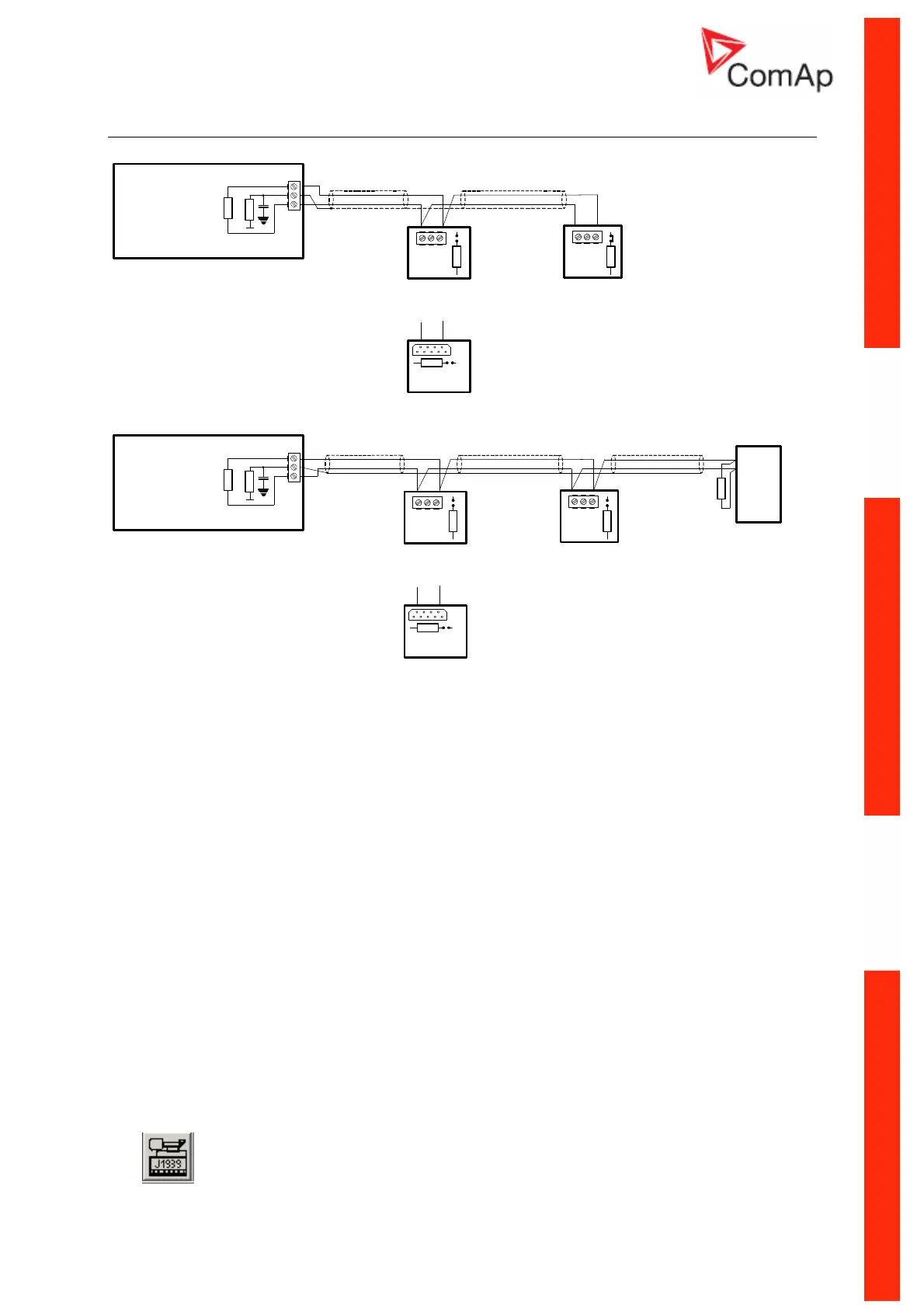
Extension modules (CAN bus) connection
CAN H
CAN L
IGL-RA15 (optional)
CAN H
CAN L
or
CAN L
CAN H
COM
IGS-PTM (optional)
CAN L
CAN H
COM
IG-IOM (optional)
5
9
CAN L
CAN H
120 ohm
EXTENSION
MODULES
H
L
120 ohm
10 ohm
15nF
COM
IL-NT
EXTENSION
MODULES
COM
CAN H
CAN L
IGL-RA15
(optional)
Engine
Electronic Control Unit
CAN H
CAN L
CAN H
CAN L
H
L
or
120 ohm
CAN L
CAN H
COM
IGS-PTM (optional)
CAN L
CAN H
COM
IG-IOM (optional)
59
CAN L
CAN H
120 ohm
CAN HI
CAN LO
120 ohm
10 ohm
15nF
COM
IL-NT
Connection rules
CAN bus line must be connected in series, from one unit to the next (no star, no cable stubs, no
branches) both ends must by the 120-ohm (internal or external) resistor terminated. Maximal CAN bus
length is up to 200 meters.
For CAN data cables details see chapter Technical data – Communication interface. CAN cable
shielding connect to IL-NT COM terminal.
IL-NT contains internal fix 120-ohm resistor and must be located on the CAN bus end.
New IG-IOM and IGS-PTM units contain internal jumper removable 120-ohm resistor (in older IOM
types are fix resistors). To be sure check resistor presence by ohmmeter. Unit with internal resistor
connect to the end of CAN line.
Following connections are supported (IOM, PTM, ECU order is not important).
IL- NT – IG-IOM
IL- NT – IGS-PTM
IL- NT – IGL-RA15
IL- NT – IG-IOM – IGL-RA15
IL- NT – IGS-PTM – IGL-RA15
It is possible to connect only one IG-IOM or IGS-PTM and one IGL-RA15 to IL-CU.
Use
button in LiteEdit configuration window to activate CAN (J1939) interface.