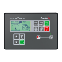
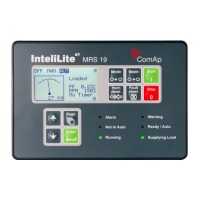
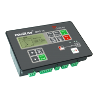
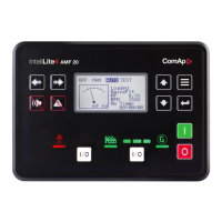
Do you have a question about the ComAp InteliLite MRS15 and is the answer not in the manual?
Highlights critical safety precautions and operational considerations for the controller.
Provides an overview of the InteliLite IL-MRS controller and its capabilities.
Diagram and description of the terminal connections for the IL-CU controller.
Provides physical dimensions and cutout information for the IL-CU controller models.
Illustrates the wiring diagram for the MRS controller, showing connections to generator and engine.
Provides instructions and guidelines for installing the InteliLite controller.
Details power supply requirements and connection considerations for the controller.
Specifies fuse requirements for the power supply connection to the controller.
Explains the need for protection diodes when connecting binary outputs to DC relays.
Provides guidelines for proper grounding to ensure controller function and safety.
Details how to connect current transformers for accurate current measurement.
Illustrates the connection for generator and mains voltage measurement.
Details recommended wiring for single-phase generator voltage and current connections.
Diagram for voltage measurement in single-phase applications.
Illustrates various connection methods for analog inputs using resistive and current sensors.
Details how to connect extension modules (IGS-PTM, IG-IOM, IGL-RA15) via CAN bus.
Specifies rules for connecting units on the CAN bus, including termination and length.
Lists the default configuration of binary outputs on the IL-CU controller.
Covers fundamental controller settings like gen-set name, power, and current.
Sets the delay for engine protections during startup.
Defines the threshold for overspeed protection.
Sets the threshold for generator overload protection.
Sets the shutdown threshold for short circuit protection.
Defines IDMT curve shape for 200% overcurrent protection.
Sets the threshold for generator current unbalance.
Sets shutdown level for generator overvoltage.
Sets shutdown level for generator undervoltage.
Sets shutdown level for generator overfrequency.
Sets shutdown level for generator underfrequency.
Details how the controller supports engines managed by an ECU.
Explains how diagnostic messages from the ECU are displayed and interpreted.
Diagrams and instructions for connecting engine control units via CAN bus.
Details CAN bus connections for starting engines.
Explains how to calibrate analog inputs and provides sensor specifications.
Identifies and describes the function of all pushbuttons and LEDs on the controller.
Details the function of each pushbutton on the operator interface.
Explains the meaning of the status LEDs on the operator interface.
Instructions for viewing and modifying controller set points.
Step-by-step guide for adjusting parameters using the controller buttons.
Describes the controller's behavior and limitations in OFF mode.
Details the operation and functions available in MAN mode.
Simplified explanation of the engine start and stop sequence.
Details the operation and functions available in AUT mode.
Explains the Sensor Fail alarm and its indication.
Details the Shut Down alarm and its effect on stopping the engine.
Explains how the controller detects and alarms on voltage phase sequence issues.
Illustrates the different operational states of the gen-set.
Provides a comprehensive list of all possible alarms and their descriptions.
Instructions for connecting the controller directly to a PC via RS232.
Overview of the ComAp LiteEdit software for controller management.
Details the Modbus communication protocol used by the controller.
Lists communication objects for controller setpoints.
Details the technical specifications of the controller's power supply.
| Operating Temperature | -20 to +70 °C |
|---|---|
| Relay Outputs | 4 |
| Frequency | 50/60 Hz |
| Power Supply | 8 to 35 V DC |
| Display | LCD |
| Communication Ports | RS485 |
| Humidity | 95% non-condensing |
| Supported Protocols | Modbus RTU |
| Power Consumption | max 3 W |


 Loading...