Do you have a question about the ComAp InteliLite MRS10 and is the answer not in the manual?
Explains the scope and purpose of the user guide.
Highlights critical safety information and warnings for operation.
Defines symbols and formatting used throughout the document.
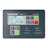
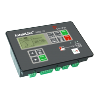
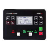
Details the InteliLite MRS controller and its system integration.
Lists all items included in the InteliLite MRS controller package.
Explains the capabilities of the I/O extension modules.
Illustrates and describes the terminal layout for the IL-CU unit.
Provides physical dimensions and cutout information for the IL-CU unit.
Presents the comprehensive wiring diagram for the MRS controller.
Provides essential steps and considerations for installing the InteliLite controller.
Details the default configuration of binary inputs on the IL-CU unit.
Provides a comprehensive list and description of available binary inputs.
Details the default configuration of binary outputs on the IL-CU unit.
Provides a comprehensive list and description of available binary outputs.
Describes the functionality and configuration of analog inputs.
Explains how to set and change the controller's password for security.
Covers fundamental parameters for gen-set and controller setup.
Configures parameters for engine overspeed detection and shutdown.
Sets warning and shutdown thresholds for Analog Input 1.
Sets warning and shutdown thresholds for Analog Input 2.
Configures parameters for generator overload detection and shutdown.
Sets parameters for generator short circuit protection.
Sets the delay for generator current unbalance alarms.
Configures high voltage shutdown and delay settings.
Configures high frequency shutdown and delay settings.
Adjusts calibrating constants for accurate analog input measurement.
Details specifications and data for IOM/PTM module sensors.
Provides calibration constants for IOM/PTM analog inputs.
Presents default configurations and characteristics for VDO sensors.
Details supported J1939 engine types for ECU control.
Explains Cummins engine integration using MODBUS protocol.
Describes how ECU diagnostic messages are displayed and interpreted.
Illustrates CAN bus connections for engines started via CAN.
Shows connections for engines not started via CAN bus.
Identifies and explains the function of all pushbuttons and LEDs.
Guides on how to select and change the gen-set operating mode.
Instructions on navigating menus to view current gen-set measurements.
Explains how to access and view the active alarm list.
Details the information displayed on the main measurement screen.
Describes the parameters shown on the generator measurement screen.
Shows the status and measured values from the ECU.
Details how ECU alarms are displayed and interpreted.
Illustrates the process for navigating menus and setting parameters.
Explains the behavior and limitations of the controller in OFF mode.
Details how to start, stop, and control the gen-set in MAN mode.
Describes the simplified engine start and stop sequence.
Explains the automatic operation and start/stop requests in AUT mode.
Describes how sensor failures are detected and indicated.
Explains the behavior and indication of warning alarms.
Details the actions taken and indication for shutdown alarms.
Detects and alarms incorrect phase sequence connection.
Detects and alarms inverted phase polarity due to wiring issues.
Provides specifics on how sensor failures are detected and displayed.
Illustrates the different operating states of the gen-set engine.
Catalogues all potential alarms with protection types and descriptions.
Explains how to connect the controller directly to a PC using RS232.
Describes the capabilities and usage of the LiteEdit configuration software.
Details the parameters and functions for Modbus communication.
Lists communication objects and their corresponding register addresses.
Lists recommended GSM modems for remote communication.
Provides steps for configuring GSM modems for use with the controller.
Guides on configuring the SIM card for data connection.
Details voltage, consumption, and voltage drop-out parameters.
Specifies environmental limits like temperature, humidity, and protection.
Explains features for operation in low temperature environments.
Provides physical dimensions and the total weight of the unit.
Lists electrical parameters for the generator output.
Details the electrical characteristics of binary inputs.
Details the electrical characteristics of analog inputs.
Describes sensor types and electrical input requirements.
Specifies the maximum communication distance and speed for RS232.
Details CAN bus length, speed, and impedance specifications.
| Input Voltage Range | 8 - 35 V DC |
|---|---|
| Digital Outputs | 4 |
| Relay Outputs | 4 |
| Display | LCD |
| Humidity | 5 to 95% non-condensing |
| Certifications | CE, UL |
| Storage Temperature | -40°C to +85°C |
| Communication Ports | RS232 |


 Loading...