13
MU02.06 MMM REV.5 11/05
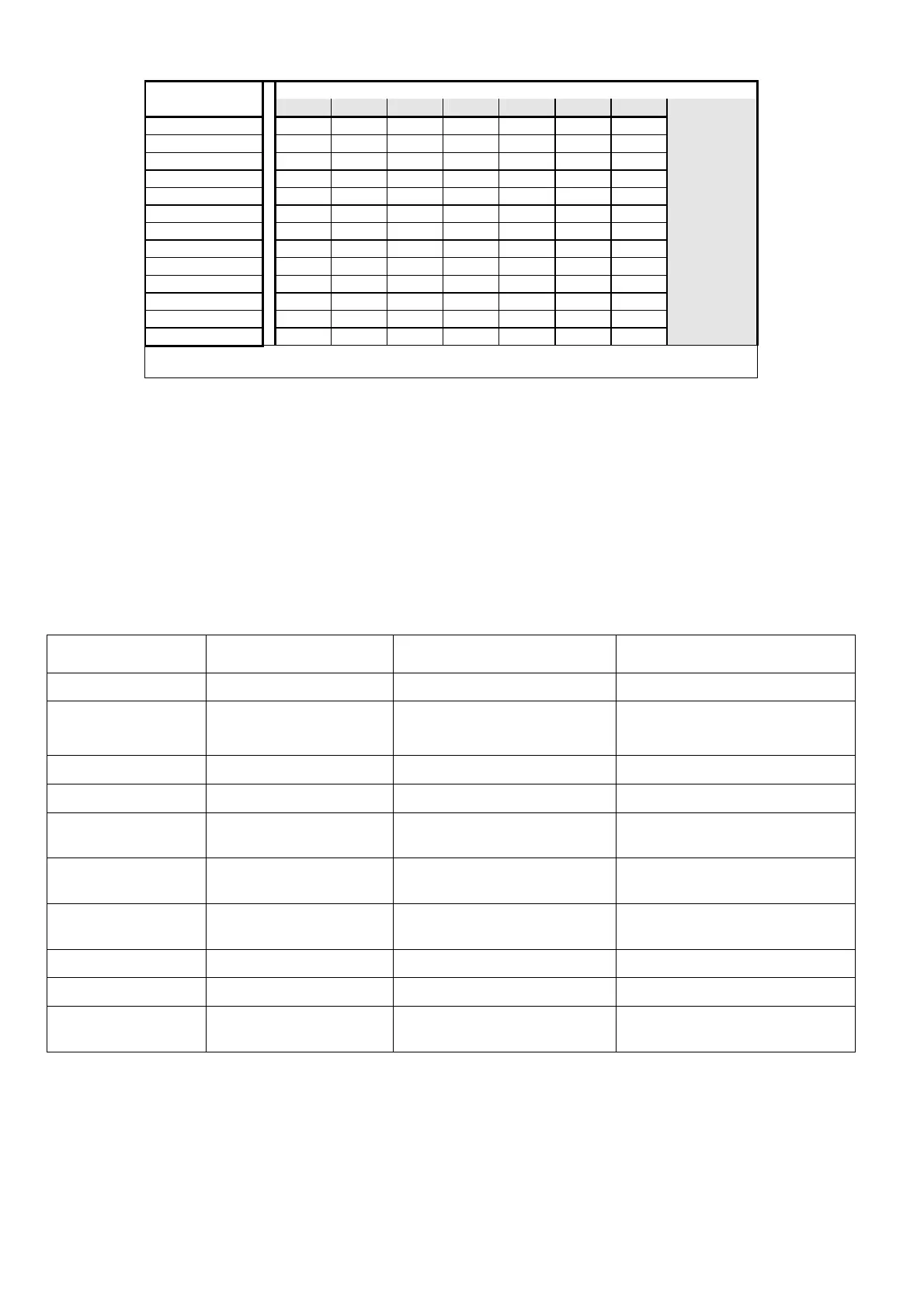
C/K settings table: choose the value by your CT and 1
st
bank reactive power
C/K 1st Capacitor Bank Power Value in kvar (C)
2,5 5 6 10 12,5 20 25
C.T.
50/5
0,25 0,50 0,50 1,00
- -
60/5
0,25 0,50 0,50 1,00 1.00
- -
80/5
0,15 0,33 0,33 0,50 1,00
- -
100/5
0,15 0,25 0,33 0,50 0,50 1,00
-
150/5
0.08 0,15 0,25 0,33 0,50 0,50 1,00
200/5
0,06 0,15 0,15 0,25 0,33 0,50 0,50
250/5
0,05 0,10 0,15 0,25 0,25 0,50 0,50
300/5
0,05 0,08 0,10 0,15 0,25 0,33 0,50
400/5
0,05 0,06 0,08 0,15 0,15 0,25 0,33
500/5
0,05 0,05 0,06 0,10 0,15 0,25 0,25
600/5
0,05 0,05 0,05 0,08 0,10 0,15 0,25
800/5
0,05 0,05 0,05 0,06 0,08 0,15 0,15
• On 220/240 VAC networks the C/K value must be doubled
• The “-“ symbol means a C.T. value too small (not acceptable)
•
••
• PF setting
After setting the C/K value, press the [SETUP] button again for 4 secs to indicate the selected PF required. At the
same the red led’s "Ind” and “Cap” will lighting. Release the “SETUP” button and use the [
+
] or [
-
] buttons to
change the selection. A P.F. of 0.95 is recommended.
• SAVE THE SETTINGS
By pressing the [SETUP] button again the C/K, P.F. values which have been selected will be saved and the
Regulator works in AUTOMATIC condition.
Note – It is not necessary to set the rated frequency, the Power Factor Regulator auto-set the mains value.
ALARMS
REFERENCE CONDITION DISPLAY INDICATIONS SITUATION
No supply voltage V < 70% Un Display off All outputs off
Low P.F. value in the
network
All banks connected
PF = IND for 15 ’.
Ind blinking
All outputs on
Low voltage V < 0,9 Un per 10 sec.
LoU blinking
Quick switch off for all outputs
High voltage V > 1,1 Un per 10 sec.
HiU blinking
Quick switch off for all outputs
Zero Current A < 50 mA RMS
for 10 secs.
A=0 blinking
Quick switch off for all outputs
(Automatic working only)
Low Current A < 350 mA RMS
for 10 secs.
LOA blinking
Inhibit output switch on
High current A > 5.5A RMS
for 10 secs.
HIA blinking
---
Leading P.F. value -0,20< PF <0,20 for 10”s
CAP blinking
Quick switch off for all outputs
Power loss V < 200 volt for 200 ms
GA4 or pinpoint blinking
Switch off all outputs and re-start
Manual forced banks Manual working selected
by the operator
Manual-button LED illuminated
Banks insertion controlled by the
operator (no AUTO)
Other operation anomalies: please check again the correctness of the installation operations and check again all points of
“operation anomalies and remedies”. A simple connection mistake can cause the P.F. Controller to function incorrectly. If the P.F.
Controller continues to work incorrectly, contact the Technical Office of the COMAR CONDENSATORI S.p.A, referring to the serial
number of the equipment (visible on the aluminium plate) and the value of measured current on the secondary circuit of the C.T.
 Loading...