DC 28V
AC 100V-240V
50Hz/60Hz
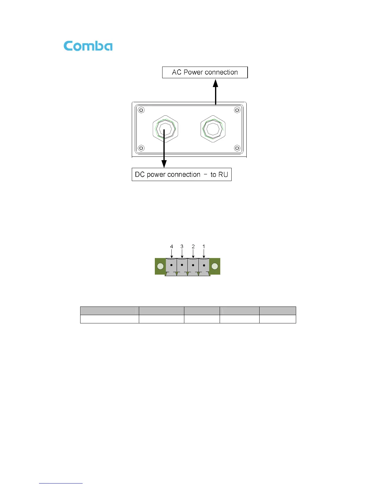
Figure 32: PSU Power Port Connection
3.5.6 RU EXTERNAL ALARM CONNECTION
For RU, this is a 4-pin connector. The following figure and table show the pin allocation and definition. Pin
numbering are shown looking-into the connector on the enclosure.
Figure 33: Pins Allocation for “EXT_ALM” Port for RU
Table 7: Pin Definition of “EXT_ALM” Port for RU
Pin number 1 2 3 4
Alarm definition EXT. Alarm 1 GND EXT. Alarm 2
GND
Note: Users need to configure Ext Alm 1~2 on WEB GUI to realize External Alarm (Refer to Chapter 5).
3.5.7 MU BTS ALARM CONNECTION
The equipment alarms can be signaled to the BTS via voltage-free relay contacts. The voltage-free relay
connections are connected to the DB-9 port “BTS_ALAM” located on the MU. The following figure and
table show the pin allocation and definition.