Comba Telecom. All Rights
568 Gibraltar Drive, Milpitas, CA 95035 | +1 408 526 0180 Ext 3 | www.combausa.com
3
Version 1.0.4
1.16.23
Cabling
The Comba’s CriticalPoint Annunciator Panel is powered and controlled by the Comba V1 or V2 Battery
Backup Unit. A three-wire communication cable is required between the Comba BBU and the
annunciator panel.
1. Switch off the AC/DC power supply in the BBU and the power switch in annunciator panel before
performing any cabling.
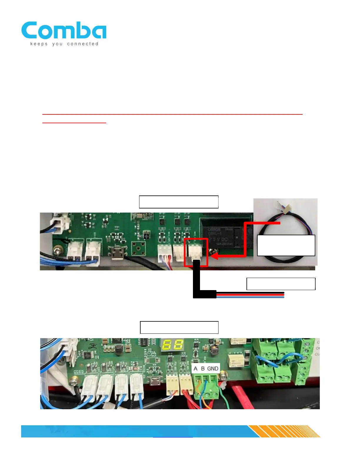
2. Communication Cable
Connect the communication pigtail cable, located in the annunciator panel accessories kit, to the BBU V1
MCU/control board. The 3-pin header is located at the bottom of the MCU/control board and to the far
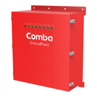
right, see picture below (NOTE: The annunciator panel pigtail is not required for the V2 BBU MCU/control
board since it incorporates a three slot phoenix connector). Extend the three-wire pigtail cable to the
annunciator panel (extension provided by the system integrator). Note: Max distance using 24-gauge
wire is 2000 feet. Max distance using 18-gauge wire is 4000 feet.