MT VCC 01
37
MT VCC 01
VIDEO INTERCOM WITH TRADITIONAL WIRING
CONNECTION DIAGRAMS
VCC/01GC Base system 1 input. Page 41
VCC/01D/C Base system 1 input with more
than 20 Diva devices. Page 42
VCC/02GC System with audio-video double input. Page 43
VCC/08GC System with an external unit,
the addition of a separate video
camera and Autostart. Page 44
VCC/04GC System with separate video camera
and Autostart. Page 45
VCC/05GC System with 2 external units of which
one is only audio and with Autostart. Page 46
VCC/05D/C System with 2 inputs (1 audio-video plus
1 audio) with more than 20 Diva users. Page 47
VCC/EN/143BC Intercommunicating system one
audio-video input with Bravo
series monitor. Page 48
VCC/EN/143D Intercommunicating system one
audio-video input with Diva
series monitor. Page 49
VCC/EN/146BC Intercommunicating system with
two external units and Autostart. Page 50
VCC/09GC System with 2 external units of which
one is only audio with combined locking. Page 51
VCC/EN/117GC/A System with 4 external units. Page 52
VCC/EN/117GC System with 4 or more external units. Page 54
VCC/39GC System with one primary audio-video
external unit and secondary audio units. Page 56
VCC/01GF Base video intercom system with
outside door calling. Page 58
VCC/011GZ Base multiple system with auxiliary
power supply for audio-video sections. Page 59
System with video port. External Vandalcom-Roma series unit. Page 60
System with video port. External Logicom series port. Page 60
System with audio port. External Vandalcom-Roma series unit. Page 60
System with audio port. External Logicom series port. Page 60
VCC/EA Lights in the external unit. Page 61
C5/T Variant for supplementary powering of
name tags for Powercom keypad. Page 61
C5/U Variant for supplementary powering of
name tags on a system equipped with
4 audio modules (Art. 1600). Page 62
VCC/GB Repeating of the call to the monitors with
relay Art. 1122/A (not timed). Page 62
VCC/BC Connection Art. 5733 for Bravo monitor. Page 63
VCC/BD Connection Art. 5734 for Bravo monitor. Page 63
VCC/DC Usage for various uses of Button
4 on a Diva monitor. Page 64
VCC/GE Exclusion of automatic starting by a
call from an external unit. Page 64
VCC/PF Servo-relay for electric locking (not timed). Page 65
VCC/GG Conversation secret
(max. 3 users for module Art. 1176). Page 65
VCC/EH Additional light for external video unit. Page 66
VCC/GJ Uses with intercom only. Page 67
VCC/GL Intercoms in parallel to the monitor
(max. 3 intercoms). Page 67
VCC/VG Connection of timer Art. 1184/A for call repeating. Page 68
VCC/PA Connection of timer Art. 1184/A for
permanent voltage electric locking. Page 69
VCC/PB Connection of timer Art. 1184/A
for safety electric locking. Page 69
VCC/GN Monitor with simultaneous start-up. Page 70
VCC/GP Supplementary power supply for monitor. Page 70
VCC/EQ Call repeating beyond the 4th monitor
or intercom. Page 71
VCC/GR Distribution of "shunted" video signal
on multiple upright columns. Page 72
VCC/GS "Cascaded" distribution of the video signal. Page 73
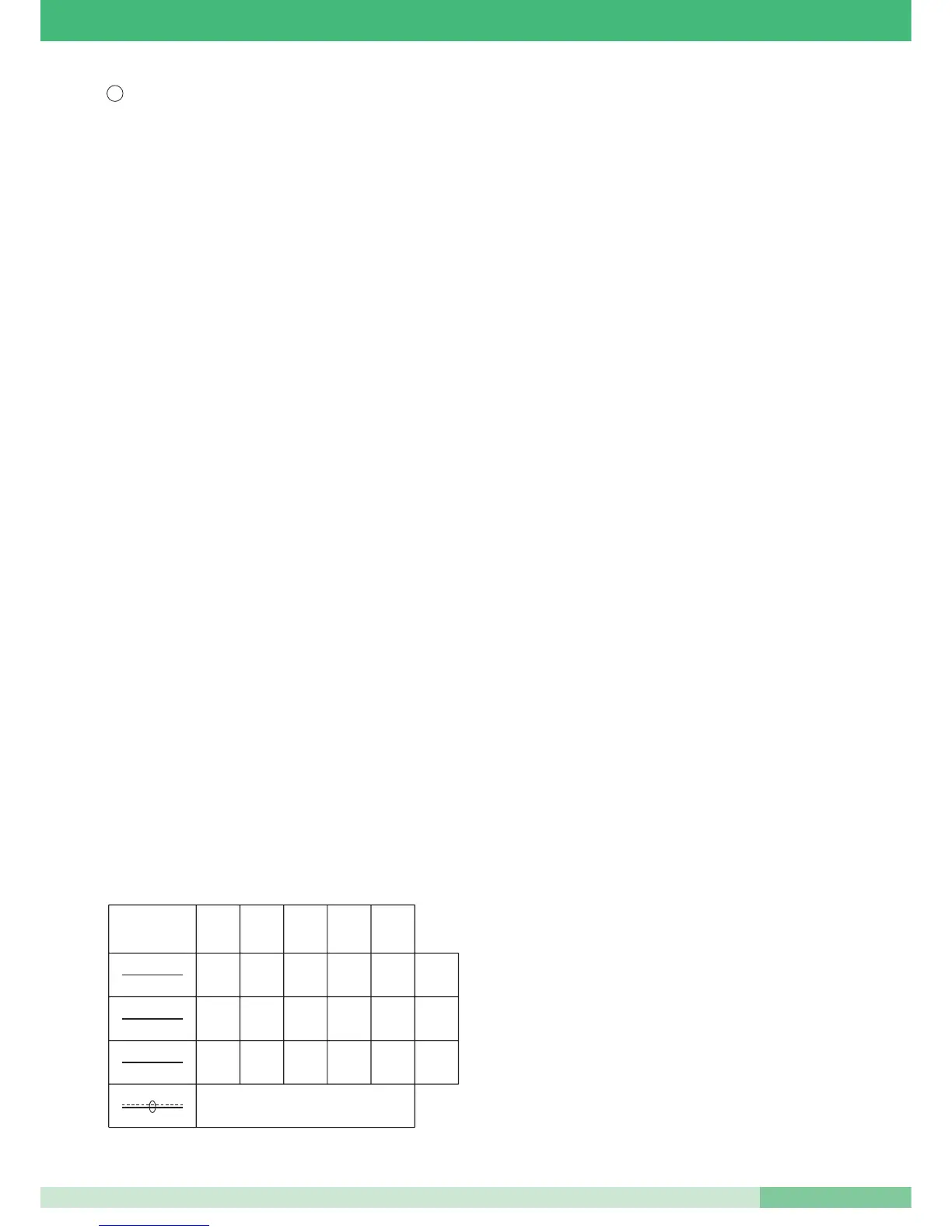
Conductors
mmmmm
20 50 100 200 300
0,30 0,50 0,80 1,00 1,50 mm
2
6/10 8/10 10/10 12/10 14/10 Ø
0,60 0,80 1,00 1,50 2,00 mm
2
9/10 10/10 12/10 14/10 16/10 Ø
0,60 0,80 1,00 1,50 2,00 mm
2
9/10 10/10 12/10 14/10 16/10 Ø
Coaxial cable
75 ohm RG 59U
4 P1 ~ ~*
+ - Monitor
VARIATIONS TO THE SYSTEM DIAGRAMS
GB
2, 3, S