Do you have a question about the COMEM R.I.S. and is the answer not in the manual?
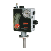
Details the pressure switch function for detecting internal pressure changes.
Covers thermometer and thermostat switches for oil temperature monitoring.
Explains the float mechanism for oil level and gas evolution detection.
Specifies protection degrees, shock, UV, and temperature resistance.
Lists voltage ratings and contact interruption capacities for device functions.
Guides the installation process, including hole size, fixing, and tightening torque.
Shows how oil level and temperature appear during normal working conditions.
Illustrates how anomalies trigger device indications for alarm and stop.
Covers essential steps before installation and general safety precautions for operation.
Explains causes and solutions for oil level drops due to temperature or vacuum.
Step-by-step guide on using a pump to restore the oil level in the device.
Identifies key parts of the R.I.S. device shown in diagrams.
Illustrates oil filler sleeve, cable gland, and magnetic components.
Provides the main external dimensions of the R.I.S. device.
Shows specific holes designated for sealing or plombing.
| Brand | COMEM |
|---|---|
| Model | R.I.S. |
| Category | Security Sensors |
| Language | English |