9
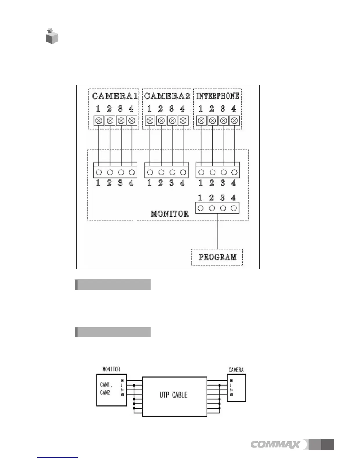
6. Wiring Diagram
Please install as the wiring diagram described below
※ Polarity of Camera connector
① RED : VOICE ② BLUE : GND ③ YELLOW : POWER(+12V) ④ WHITE : VIDEO SIGNAL
Each device should be connected by separated cables.
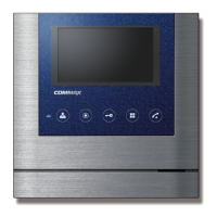
If you use UTP CABLE[CAT.5] for Camera1 and Camera2, 2 lines of UTP CABLE
are required.
Wiring precautions
If you use UTP CABLE[CAT.5], connect the rest 4 lines to GND after connecting 4 lines
between Monitor and interphone.
DOOR Camera Wiring