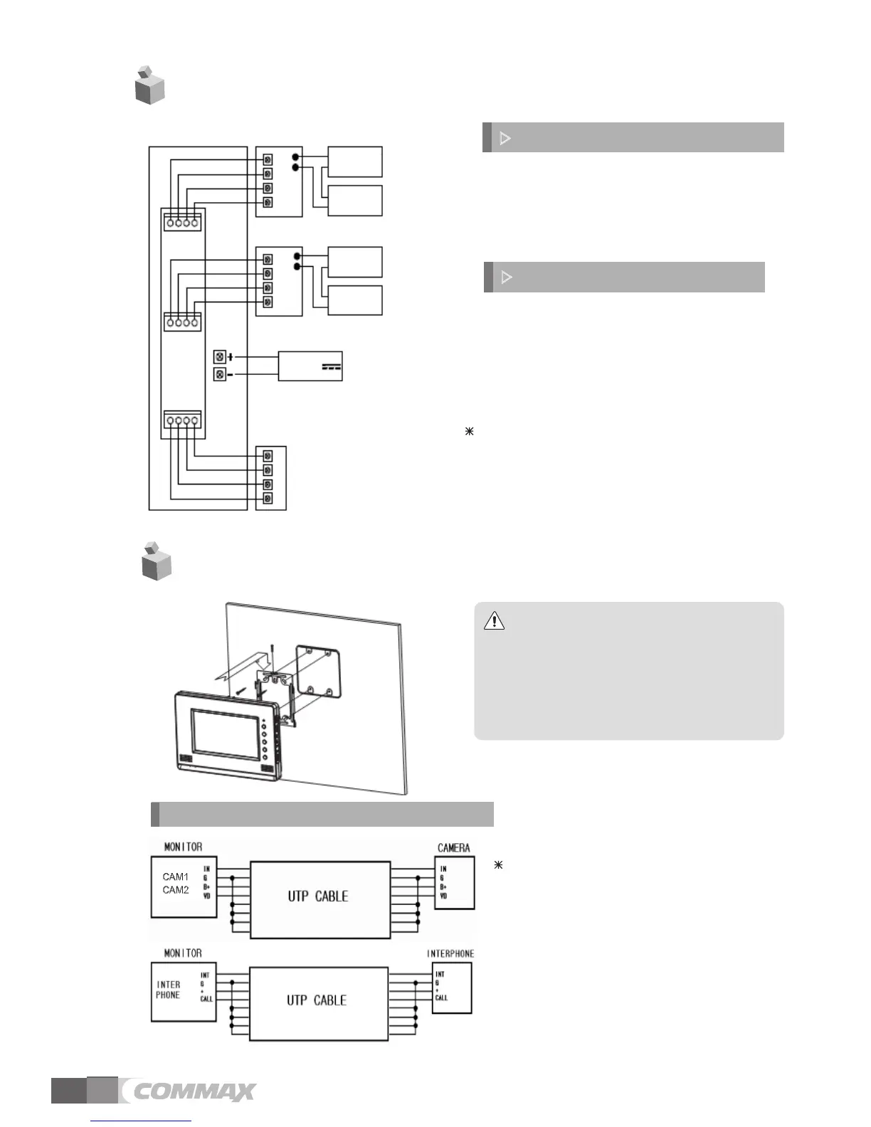
1. Red: Talk (Audio)
2. Blue: GND
3. Yellow: Power (+12V)
4. White: Video
▷
Polarity of the camera connector
1. Red: Talk (Audio)
2. Blue: GND
3. Yellow: Power (+14V)
4. White: Call signal
▷
Polarity of interphone connector
4. Wiring and Connection Instructions
.
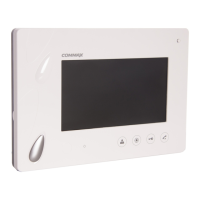
Installation
5
Note
① Avoid the range of direct sunlight
② Recommended height is pertinent
from 1450 ~ 1500mm
③ Avoid the installation near magnetic
activity, humid temperatures and gas
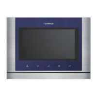
If you use UTP CABLE[CAT.5], connect
4 lines between monitor and interphone.
the rest 4 lines to GND after connecting
DOOR CAMERA & INTERPHONE Wiring
Each device should be connected by
If you use UTP CABLE[CAT.5] for
separated cables.
CAMERA1and CAMERA2, 2 lines of UTP
cable are required.
4
Program
1
CAMERA1
Door
Release
Adaptor
Power
Adaptor
Power
Door
Release
Adaptor
Power
Adaptor
Power
CDV-70A
1 2 3 4
Interphone
CAMERA2
2
3
4
1
2
3
4
1
2
3
4
1 2 3 4
1 2 3 4
17V-30V
(Only CDV-70AD)