1930 SERVICE MANUAL
SERVICE ADJUSTMENTS (Continued)
Static Convergence Adjustment
Dynamic Convergence Adjustment
1. Inject a cross-hatch pattern signal and allow a 10
minute warm-up period.
2. Turn off the green gun by disconnecting R728. Turn
locking ring (B) counterclockwise.
3. Slowly spread, and if necessary, rotate the 4-pole
magnetic rings (C) to converge red and blue lines at
the center of the screen.
4. Reconnect R728 to turn on the green gun and
disconnect R735 to turn off the blue gun.
5. Slowly spread, and if necessary, rotate the 6-pole
magnectic rings (D) to converge the red and green
lines at the center of the screen.
6. Reconnect R735 to turn on the blue gun.
7. For optimum performance, repeat steps 1 through 6.
Proceed to the Dynamic Convergence Adjustment.
12
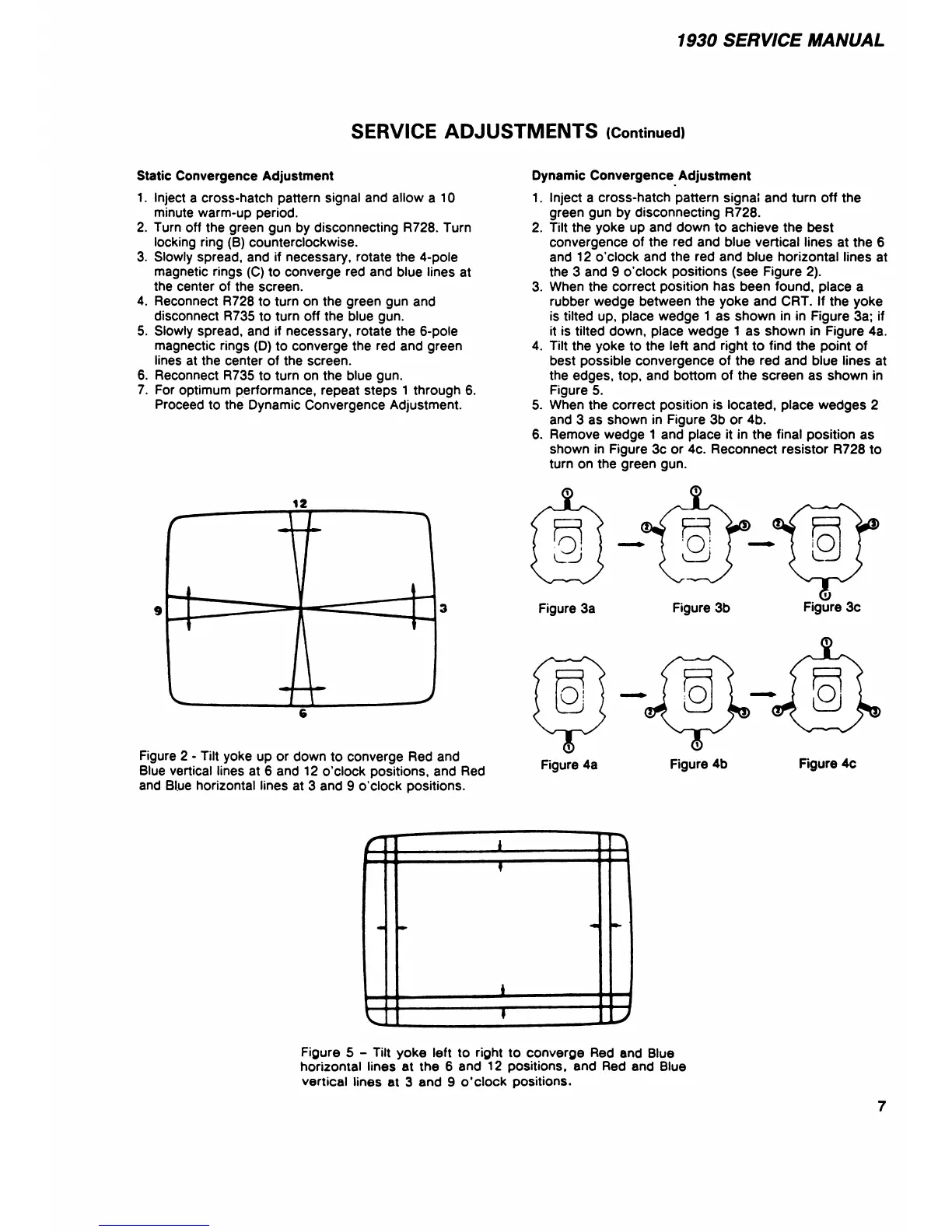
Figure 2 - Tilt yoke up or down to converge Red and
Blue vertical lines at 6 and 12 o'clock positions, and Red
and Blue horizontal lines at 3 and 9 o'clock positions.
1. Inject a cross-hatch pattern signal and turn off the
green gun by disconnecting R728.
2. Tilt the yoke up and down to achieve the best
convergence of the red and blue vertical lines at the 6
and 12 o’clock and the red and blue horizontal lines at
the 3 and 9 o’clock positions (see Figure 2).
3. When the correct position has been found, place a
rubber wedge between the yoke and CRT. If the yoke
is tilted up, place wedge 1 as shown in in Figure 3a; if
it is tilted down, place wedge 1 as shown in Figure 4a.
4. Tilt the yoke to the left and right to find the point of
best possible convergence of the red and blue lines at
the edges, top, and bottom of the screen as shown in
Figure 5.
5. When the correct position is located, place wedges 2
and 3 as shown in Figure 3b or 4b.
6. Remove wedge 1 and place it in the final position as
shown in Figure 3c or 4c. Reconnect resistor R728 to
turn on the green gun.
Figure 3a Figure 3b Figure 3c
Figure 4a Figure 4b Figure 4c
Figure 5 - Tilt yoke left to right to converge Red and Blue
horizontal lines at the 6 and 12 positions, and Red and Blue
vertical lines at 3 and 9 o’clock positions.
7