1930 SERVICE MANUAL
SERVICE ADJUSTMENTS (Continued)
Note: The following adjustments need only be performed
if the CRT has been replaced. Minor corrections for
purity and convergence may be accomplished through,
the use of the Purity and Convergence Assembly located
on the neck of the CRT.
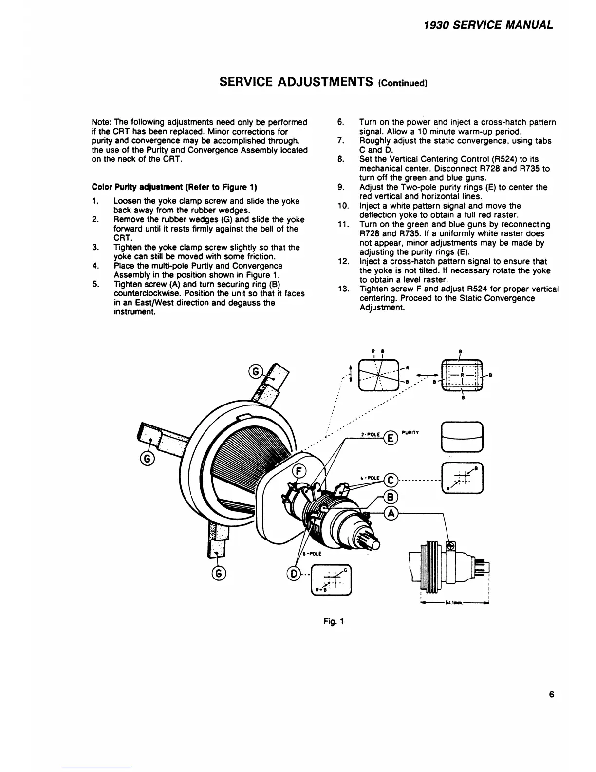
Color Purity adjustment (Refer to Figure 1)
1. Loosen the yoke clamp screw and slide the yoke
back away from the rubber wedges.
2. Remove the rubber wedges (G) and slide the yoke
forward until it rests firmly against the bell of the
CRT.
3. Tighten the yoke clamp screw slightly so that the
yoke can still be moved with some friction.
4. Place the multi-pole Purtiy and Convergence
Assembly in the position shown in Figure 1.
5. Tighten screw (A) and turn securing ring (B)
counterclockwise. Position the unit so that it faces
in an East/West direction and degauss the
instrument.
6. Turn on the power and inject a cross-hatch pattern
signal. Allow a 10 minute warm-up period.
7. Roughly adjust the static convergence, using tabs
C and D.
8. Set the Vertical Centering Control (R524) to its
mechanical center. Disconnect R728 and R735 to
turn off the green and blue guns.
9. Adjust the Two-pole purity rings (E) to center the
red vertical and horizontal lines.
10. Inject a white pattern signal and move the
deflection yoke to obtain a full red raster.
11. Turn on the green and blue guns by reconnecting
R728 and R735. If a uniformly white raster does
not appear, minor adjustments may be made by
adjusting the purity rings (E).
12. Inject a cross-hatch pattern signal to ensure that
the yoke is not tilted. If necessary rotate the yoke
to obtain a level raster.
13. Tighten screw F and adjust R524 for proper vertical
centering. Proceed to the Static Convergence
Adjustment.
* B
i i
Fig. 1
6