Centronics standards
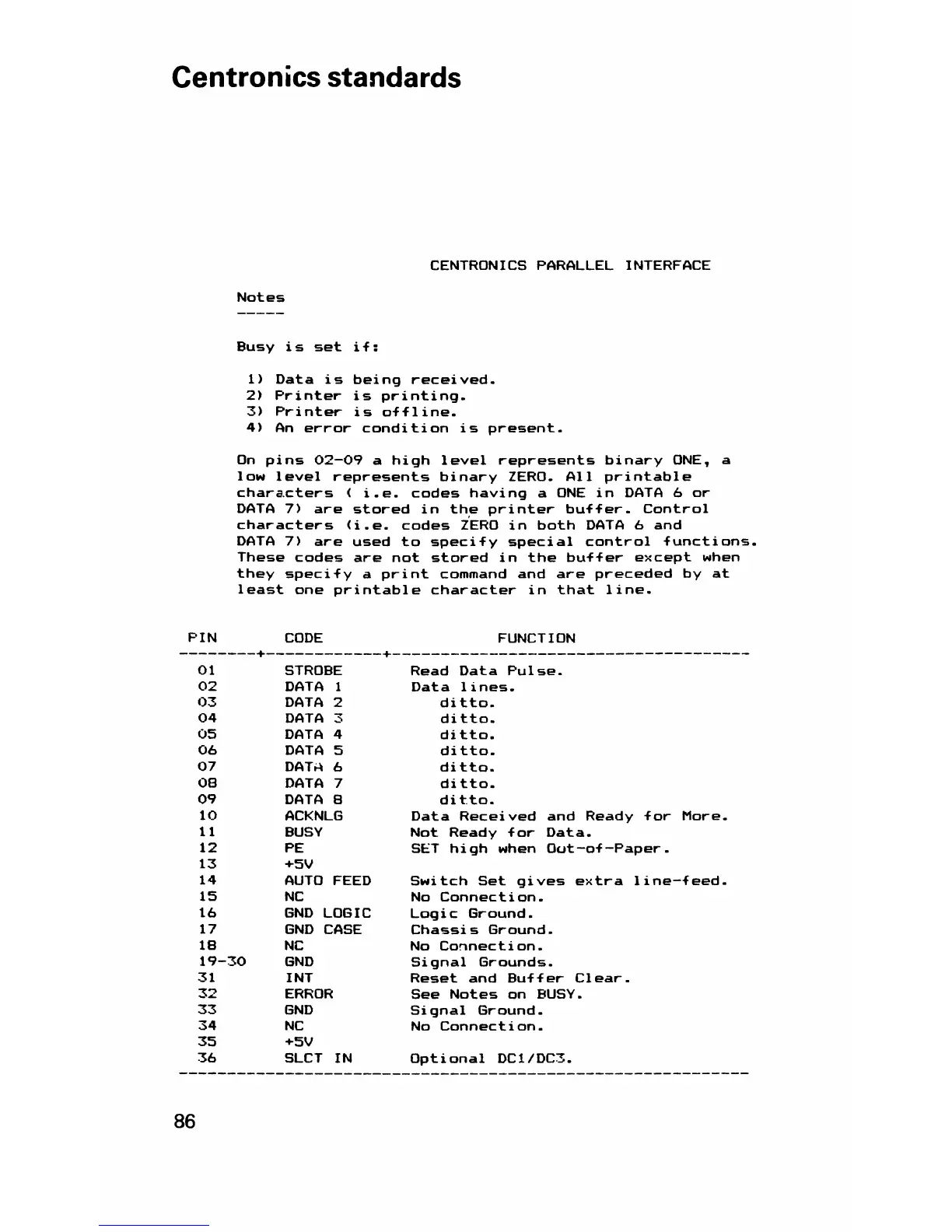
CENTRONICS PARALLEL INTERFACE
Notes
Busy is set if:
1)
2)
3)
4)
Data is being received.
Printer is printing.
Printer is offline.
An error condition is present.
On pins 02—09 a high level represents binary ONE, a
low level represents binary ZERO. All printable
characters ( i.e. codes having a ONE in DATA 6 or
DATA 7) are stored in the printer buffer. Control
characters (i.e. codes ZERO in both DATA 6 and
DATA 7) are used to specify special control functions.
These codes are not stored in the buffer except when
they specify a print command and are preceded by at
least one printable character in that line.
PIN
CODE
FUNCTION
01
STROBE Read Data Pulse.
02
DATA 1 Data lines.
03 DATA 2 ditto.
04
DATA 3 ditto.
05 DATA 4 ditto.
06 DATA 5 ditto.
07
DATA 6
ditto.
00
DATA 7 ditto.
09
DATA B
ditto.
10
ACKNLG Data Received and Ready for 1
11 BUSY
Not Ready for Data.
12
PE SET high when Oot-of-Paper.
13
+5V
14
AUTO FEED Switch Set gives extra line—
15
NC No Connection.
16
GND LOGIC Logic Ground.
17
GND CASE
Chassis Ground.
18
NC No Connection.
19-30
GND Signal Grounds.
31
INT
Reset and Buffer Clear.
32
ERROR See Notes on BUSY.
33 GND Signal Ground.
34
NC No Connection.
35 +5V
36 SLCT IN Optional DC1/DC3.
86