Manual for ION™-M7P/17P (M-cab)
& Subassemblies
Page 20 MF0145A7A_uc_FCC_modif.doc
4.1.3. Pole-Mounting Procedure
Standard mounting hardware cannot be used to mount the Remote Unit to a pole, a
column or other similar structures. Additional hardware must be used for this type of
installation. Such a pole-mounting kit could include two threaded rods M8, two
U-beams and mounting material like bolts and nuts.
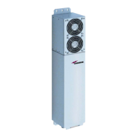
figure 4-2 Pole-mounting kit
Use the screw bands to fasten the two U-beams to the pole as illustrated in figure
4-3 Pole mounting.
Note: When fastening the U-beams make sure that they are installed
congruently and not at an angle to each other. To determine the
distance between the beams refer to 4.1.2 Wall-Mounting Procedure
for measurements.
Hang the mounting brackets of the Remote Unit into the threaded bolts of the
U-beam, and fasten them immediately using the washers and nuts.
Ensure that there is free access to the electrical connections as well as to the
cabinet. The approved bending radius of the connected cables must not be
exceeded.
 Loading...