Manual for ION™-M7P/17P (M-cab)
& Subassemblies
Page 37 MF0145A7A_uc_FCC_modif.doc
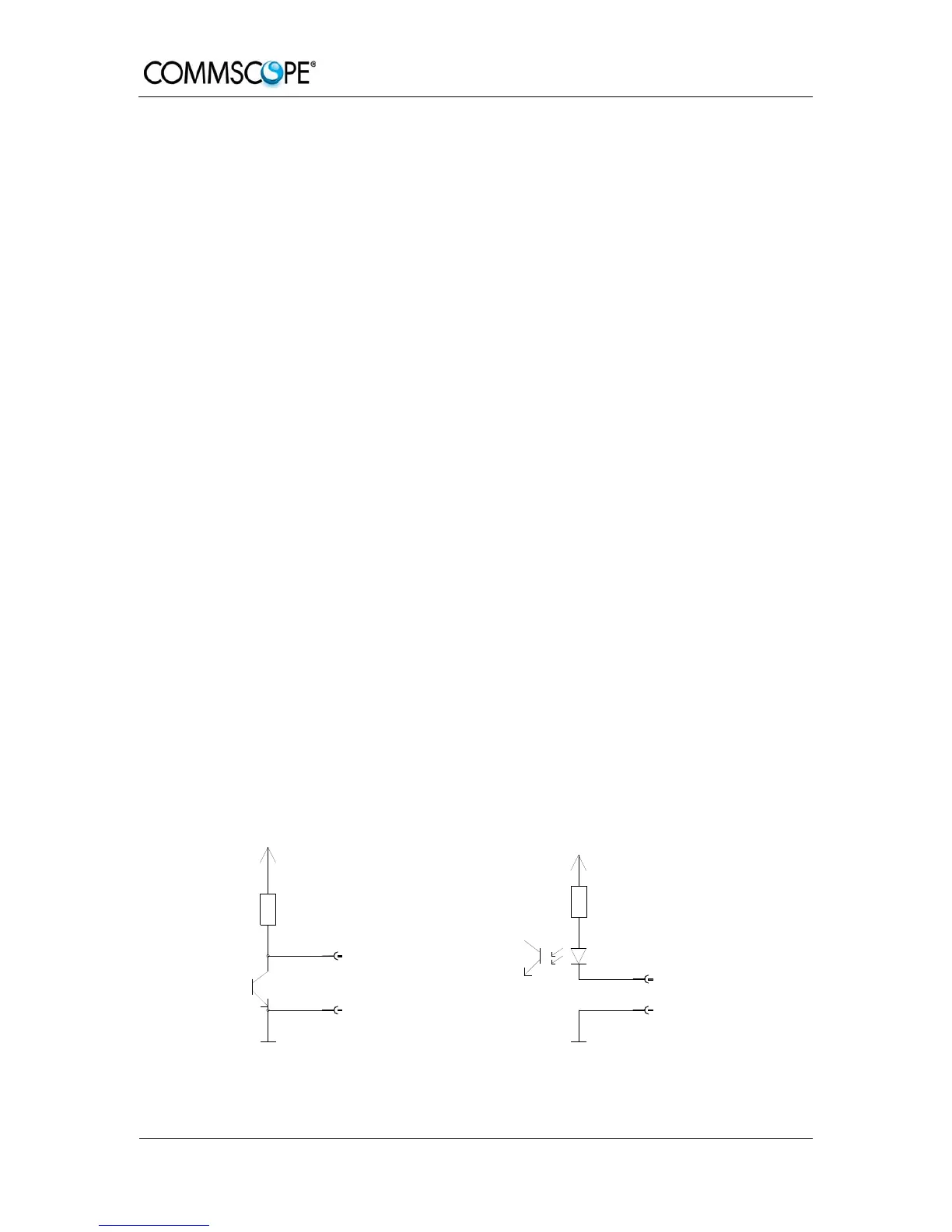
The alarm outputs (open collector output 5 V / 1 mA) are normally low. In case of an
alarm they are high active (5 V). They can be used to monitor alarms with an external
alarm indicator.
The +28 V pin (for its location see figure 5-2 Flange connector, 7 poles) is protected
by a 500 mA thermoswitch. In case of exceeding this current between pin 7 and GND
and/or in case of a failure of the VSWR module, the thermoswitch turns into a high-
resistive status. In this case no fuse needs to be replaced. Just wait a few minutes
until the thermoswitch reaches the normal operating temperature again.
Note: The manufacturer / supplier of this system accepts no liability for
damage caused by equipment connected to external outputs or by
effects from such equipment.
As accessory equipment the alarm kit is available to connect external devices to the
external alarm inputs and outputs. For the exact ID No., please refer to section 7.3
Spare Parts.
With the external alarm inputs it is possible to monitor the status of connected
devices, e.g. a UPS, via software. All alarm inputs are normally high (5 V) without
connection. The polarity (high/ low) can be set via the software at the Master Unit (for
details please see according software manual).
The device to be monitored must be connected so that the alarm contacts will be
closed in case of an alarm (I max = 8 mA). The alarm inputs are potential-free with
common ground.
Subminiature circular connectors series 712 with five and seven contacts, which are
contained in the alarm kit, can be ordered directly from the Binder Connector Group,
the manufacturer, or indirectly from Andrew Solutions. For the ID No. of the alarm kit
see section 7.3 Spare Parts.
V1651A1
Alarm output
Alarm GND
Alarm GND
Alarm GND
Alarm GND
Alarm input
ION-M alarm outputs
4700R
+5 V
ION-M alarm inputs
+5 V
560R
figure 5-3 Alarm inputs and outputs, standard
 Loading...