Manual for ION™-M7P/17P (M-cab)
& Subassemblies
Page 36 MF0145A7A_uc_FCC_modif.doc
Alarms directly related to RU:
Power 28 V
Change power supply (RUs with door).
Replace the affected Remote Unit.
Temperature
Reduce environmental temperature.
Eliminate thermal short circuit.
Fan
Disconnect and connect mains. Fans
should run. If not, replace the fans at
RU.
I²C Disconnect and connect mains.
Optical alarm Tx Exchange RU.
Red
mplifier “Power
Down”
(MU: Change amplifier setting at MU
controller).
Status LED off Mains
Check power switch inside of RU (RUs
with door).
Check mains cabling.
Check mains power.
table 5-1 Status LED alarms
For the position of the status LED see section 4.2.2 Connections.
Explicit troubleshooting is available in the MU software (software manual or WEB
Interface).
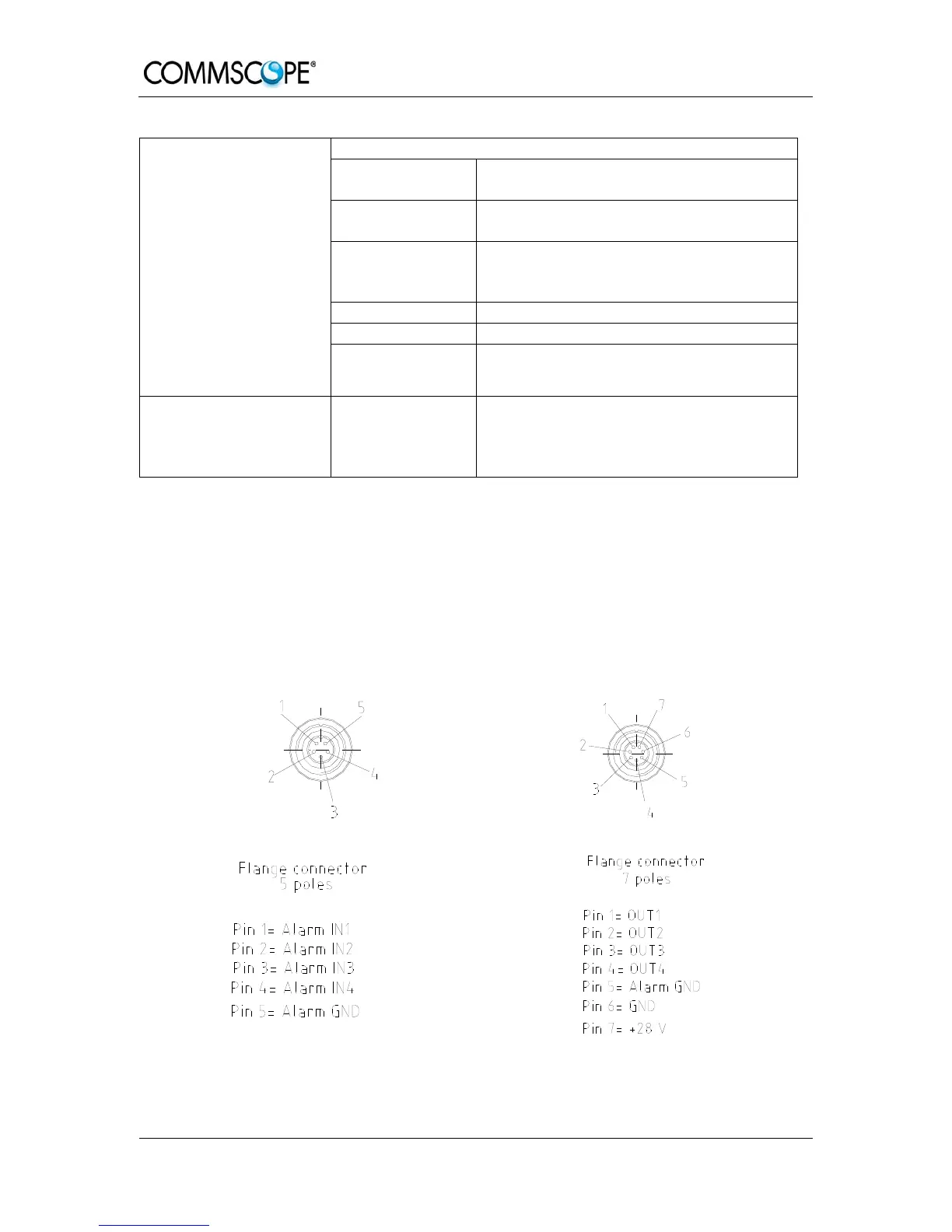
5.5. EXTERNAL ALARM INPUTS AND OUTPUTS
G1038Z0
G1038Z0
figure 5-1 Flange connector, 5 poles figure 5-2 Flange connector, 7 poles
 Loading...