B
Rev
RE
Status
Model Version
04
01
Version
01
A
Status
Rev
2 of 14
page
Bulletin
AE01B-A0599-001
Installation Instructions
MT050C
Section 1 - General Information
1.1 - Introduction
This manual contains the information needed to install, operate and maintain the MT050C Series DryLine®
dehydrator. Please take the time to read this manual before attempting to operate or service the unit.
1.2 - Description
MT050C Series DryLine® dehydrators provide dry air for pressurizing small (up to 60 cubic feet, or 1700 liters, in
volume) antenna and transmission line systems. The dehydrators produce -50ºF (-45ºC) dew point dry air at an
output rate of 0.12 cubic feet (3.4 liters) per minute.
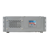
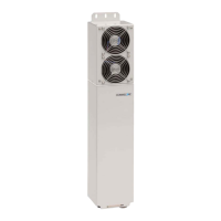
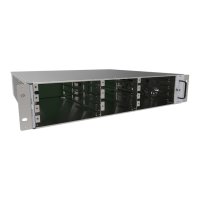
Each dehydrator consists of an electrically-driven air compressor, a membrane dryer assembly, an automatic
transmission line pressure sensing system and alarm outputs housed in a rigid metal chassis. It is designed to
mount in a standard 19” equipment rack, wall, or on a shelf. The front panel features a control interface with display
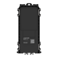
for alarms and pressure. For easy serviceability, power connections, alarm output connections and all filter elements
are accessible from the rear or front of the unit.
The MT050C maintains transmission line pressures at 3.0 psig (20.7 kPa). It is intended for standard microwave
antenna applications and any other transmission line pressurization requirement that supports a medium
pressure limit.
1.3 - Operation
The MT050C DryLine® dehydrator, while similar in moisture removal technology, operates differently than some
of the DryLine® series of dehydrators. In order to provide a constant supply of dry air to small air volume systems,
and to maintain an acceptable dryness level in the product air stream, a high-pressure reservoir tank is utilized.
This reservoir tank is connected to a pressure regulator and orifice to yield a fixed output pressure of 3.0 psig and
a nominal flow rate of 0.12 SCFM. In addition to supplying the output air, the reservoir tank also provides the dry
air for the feedback loop. The feedback loop is necessary to maintain the dryness of the membrane cartridge.
During normal operation, the feedback loop will cause the pressure to slowly drop in the internal reservoir tank, and
the MT050C compressor will cycle automatically. These cycles will take place regardless of the system volume or
condition of the transmission line the dehydrator is connected to. The rate of these cycles, however, may vary
slightly.
When connected to a very tight system, or the output is capped, the dehydrator will cycle approximately every 60
minutes and maintain 3.0 psig system pressure. When open to atmosphere, the dehydrator will cycle approximately
every 3 minutes while providing close to 0.12 SCFM of dry air. A system that leaks will have a cycle time
somewhere in between, depending on the severity of the leaks.
The display will also reflect a pressure between 0 and 3.0 psig while the output flow is between 0 and 0.12 SCFM.
The pressure sensor tracks the pressure beyond the flow control orifice and will show the actual pressure in the
transmission lines (or to the distribution manifold).
NOTICE: The installation, maintenance or removal of pressurization equipment requires qualified
and experienced personnel. Pressurization systems should be inspected once per year by
qualified technicians to verify proper installation, maintenance and condition of equipment.
Commscope disclaims any liability or responsibility for the result of improper or unsafe installation
practices.