B
Rev
RE
Status
Model Version
04
01
Version
01
A
Status
Rev
5 of 14
page
Bulletin
AE01B-A0599-001
Installation Instructions
MT050C
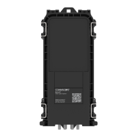
BLANK PLATE
PCB PLATE
RACK-MOUNT
MOUNTING BRACKETS
WALL-MOUNT
PCB PLATE
MOUNTING
BRACKET
2.1 - Mounting Configuration
Section 2 - Installation
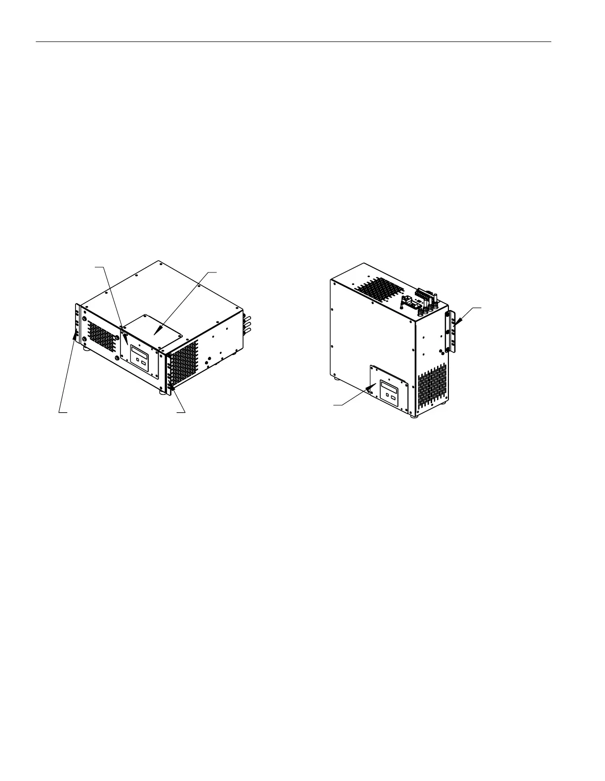
The MT050C dehydrator is packaged in the rack-mount configuration and requires no modification for mounting into a standard
19" equipment rack. This unit can be easily modified for a wall-mounting configuration as well.
To set the MT050C up for wall-mounting, a #2 Phillips head screwdriver is required. Remove the blank plate indicated
in the image below and set aside. Remove the four screws from the PCB plate and set aside. Move the PCB plate to the area
where the blank plate was originally. Screw the PCB plate into place. Now install the blank plate in the empty space where the
PCB plate used to be.
The vibration isolators on the bottom of the unit can be moved to the front panel, which will be the bottom
of the unit in the wall-mount configuration. The isolators are for mounting the unit to a bench or shelf and are not necessary
for rack or wall-mounting configurations.
Remove the mounting brackets from the unit and relocate them into the position shown for wall-mounting the dehydrator.
2.2 - Controls and Display
Familiarize yourself with the controls and display prior to installing or testing the MT050C dehydrator. The default system
password is 1111.
Select Button - Advances display (scrolls ahead) to the next display or program mode without changing any values in the
microprocessor memory.
Enter Button - Enters the values displayed into the microprocessor memory and advances the display to the next screen.
Up Arrow Button - Increases highlighted numerical information on the display. When held down, scrolling speed will increase.
Down Arrow Button - Decreases highlighted numerical information on the display. When held down, scrolling speed will
increase.
View Log Button - Will show the event log. The log is shown with the most recent event at the top. Scroll down for event
history.
Event Log Codes
EV = 0 Power Up
EV = 1 High Humidity Alarm
EV = 2 Excess Run Time Alarm
EV = 3 Low Pressure Alarm
EV = 4 High Pressure Alarm - This alarm does not report to alarm contacts.
EV = 5 Compressor Fault - Unit will require evaluation or compressor overhaul or replacement.
EV = 6 Log Cleared
EV = 7 Powering Down
EV = 8 Compressor Lifetime EEPROM failure - Unit will require a new control board.