Installing Additional Drives
When installing additional drives, follow these guidelines:
●
The primary Serial ATA (SATA) hard drive must be connected to the dark blue primary SATA
connector on the system board labeled SATA0.
●
Connect the first SATA optical drive to the white SATA connector on the system board labeled
SATA1.
●
Always populate the dark blue SATA0 and white SATA1 connectors before the light blue SATA2
and orange SATA3 connectors.
●
Connect a second SATA optical drive to the orange SATA3 connector.
●
Connect additional SATA hard drives to the next available (unpopulated) SATA connector on the
system board in the following order: SATA0, SATA1, SATA3, SATA2.
●
Connect a diskette drive to the connector labeled FDD1.
●
Connect a media card reader to the USB connector labeled JUSB2.
●
The system does not support Parallel ATA (PATA) optical drives or PATA hard drives.
●
You may install either a third-height or a half-height drive into a half-height bay.
●
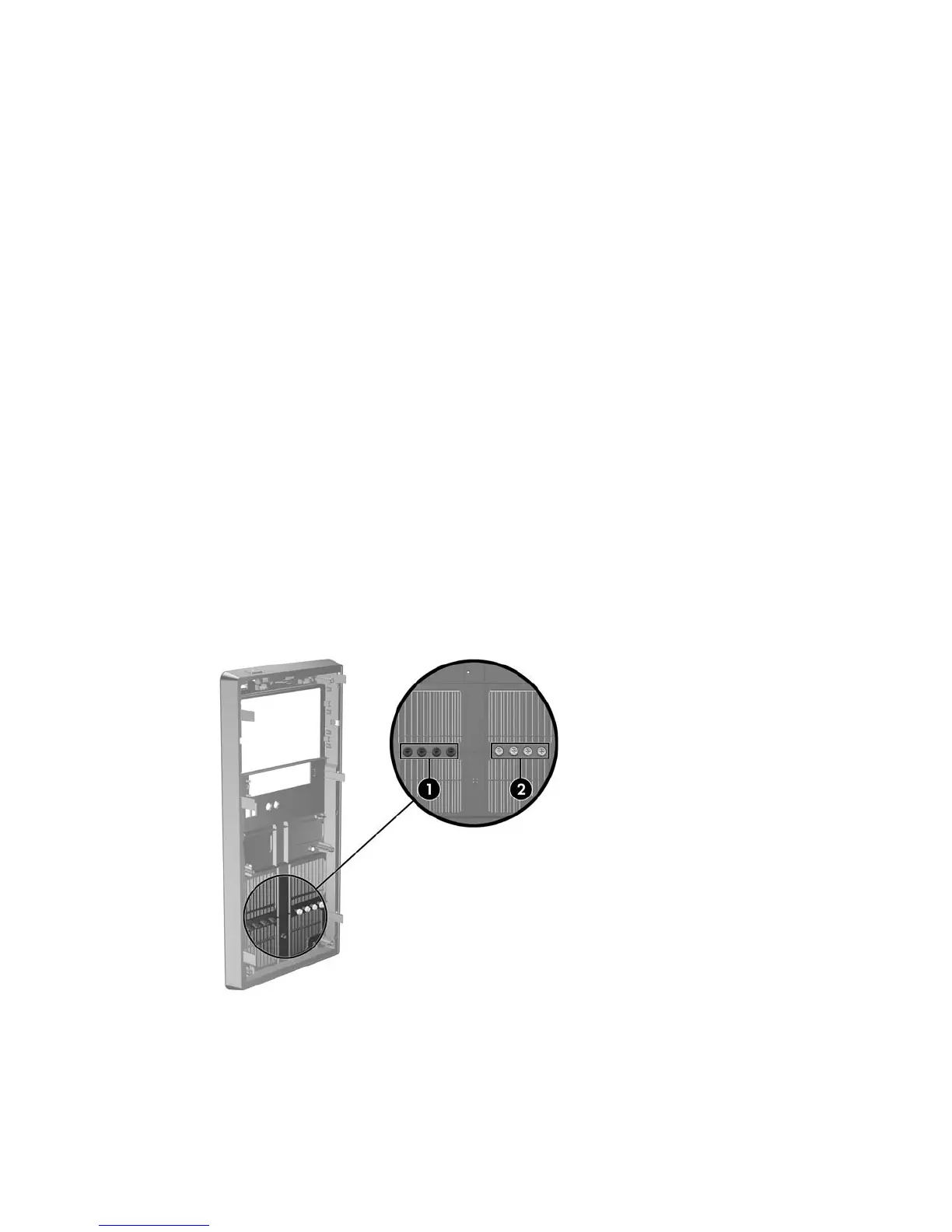
If needed, HP has provided extra drive retainer screws on the interior of the front bezel that are
used to secure the drives in the drive cage. Hard drives use 6-32 standard screws. All other drives
use M3 metric screws. The HP-supplied M3 metric guide screws (1) are black. The HP-supplied
6-32 standard screws (2) are silver.
Figure 2-16 Extra Drive Retainer Screws Location
24 Chapter 2 Hardware Upgrades