If the unit is provided with sensing cable type leak detection system, use specific manual provided by the
manufacturer to install the complete system. Alarm relay dry contact from sensing cable type leak
detection system can be connected to the digital input for condensate alarm of unit controller. Use
24VAC power from the unit terminal block for this alarm input
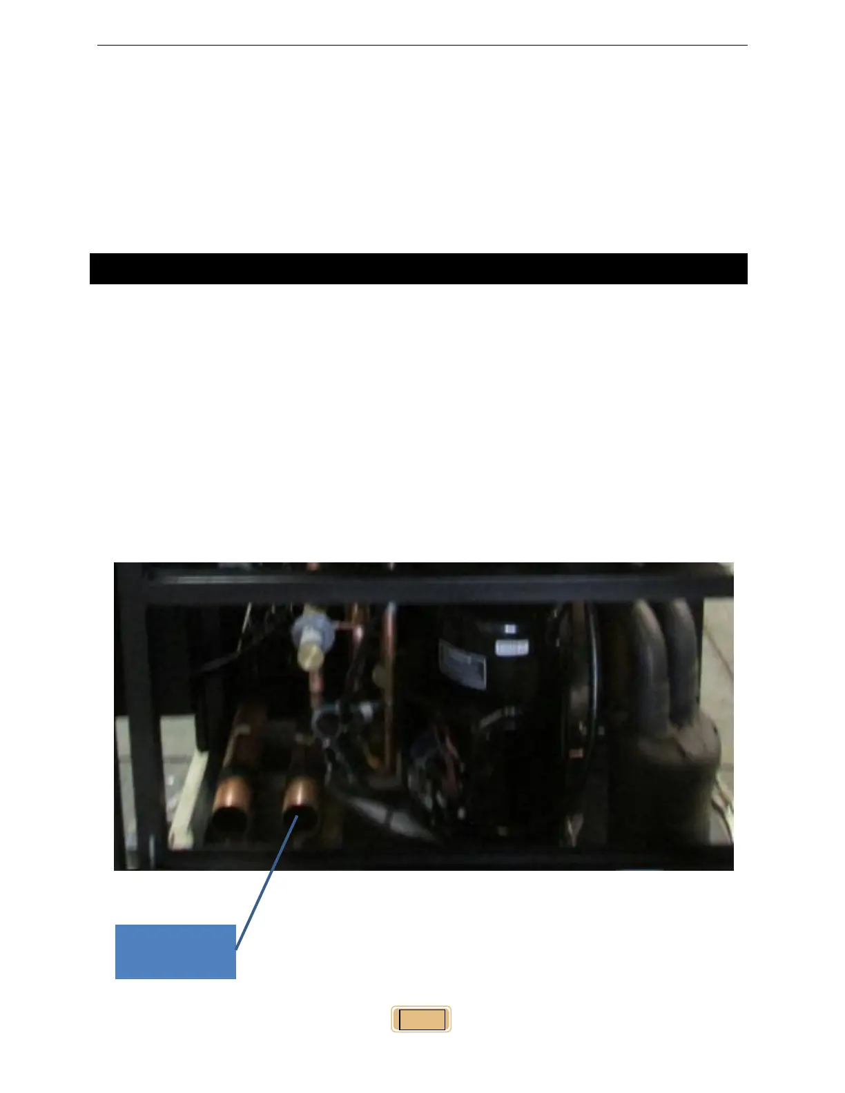
14 PIPING CONNECTION LAYOUT
14.1 WATER/GLYCOL LINE CONNECTION
Note: Water side operating pressure not to exceed 125 PSIG. Optional high pressure rated valve is
available from the factory.
Unless specified water/glycol piping connection s are located on the left bottom corner of the standard
unit. On standard connection, field pipings are from the side of the unit on the bottom of the side door
by making knockouts. Alternatively field piping access can be from the bottom of the unit with optional
floorstand shall be used to support the unit.
After all connections are made to the unit, close-off and seal all air openings around the pipes using
tubing insulation material such Armaflex.
Figure 14. Piping Connection
 Loading...