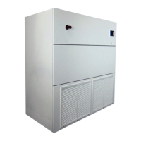
Figure 8. Unit Dimensions-Standard Unit shown ........................................................................................ 28
Figure 9 Sample Unit Shown* ..................................................................................................................... 29
Figure 10. Condenser and Reheat elements access ................................................................................... 30
Figure 11. Unit Side Layout ......................................................................................................................... 30
Figure 12. Rear Open Floor Stand ............................................................................................................... 31
Figure 13 - Terminal Block with System Cut-Out ........................................................................................ 32
Figure 14. Piping Connection ...................................................................................................................... 33
Figure 15: Air Pressure Differential Switch ................................................................................................. 35

 Loading...