Re‐FlashingYourCDM‐570A/570ALSatelliteModem 2 FLG‐CDM570ARevision1
II. GettingStarted:PreparefortheFirmwareDownload
If you have already completed this procedure using CEFD document “Re‐Flashing Your
Comtech EF Data Product” (CEFD P/N FLG‐FLASHINTRO_rx.pdf, where ‘x’ is the document
revisionnumber),continuetoSectionIII.DownloadingandExtractingtheFirmwareUpdate
.
1) First,identifytheCDM‐570A/Lfirmware(number/revisionletter/versionnumber)andtheassigned
EthernetTrafficIPAddress .
User‐supplieditemsneeded:
AMicrosoftWindows‐basedPC,equippedwithavailableserialandEthernetports;acompatible
Webbrowser(e.g.,InternetExplorer);andaterminalemulatorprogram(e.g.,TeraTerm
or
HyperTerminal).
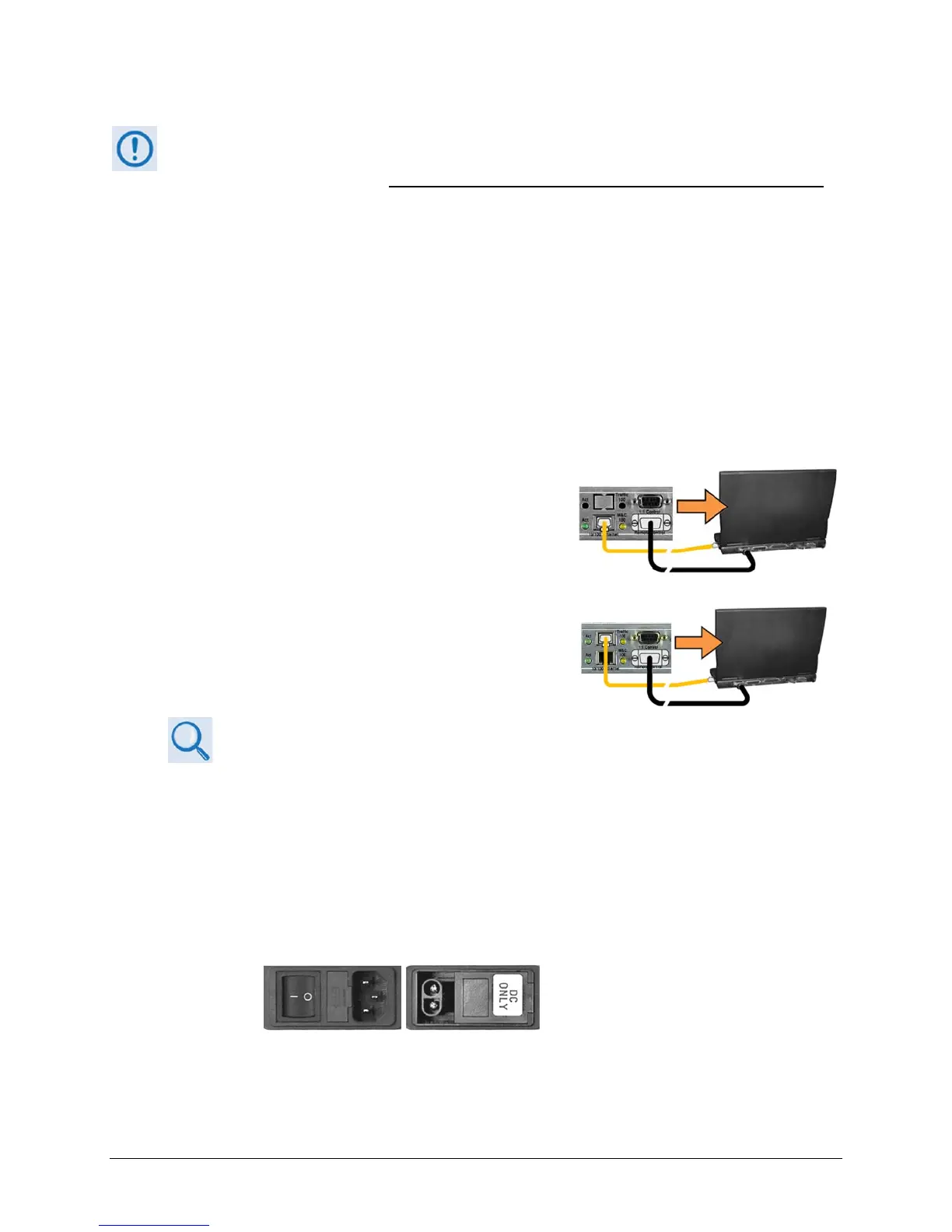
A9‐pinserialcableandastandardCAT5EthernetcabletoconnecttheCDM‐570A/LtotheUserPC.
A. Usethe9‐pinserialcabletoconnecttheCDM‐570A/L
‘RemoteControl’porttoaserialportontheUserPC.
UseanEthernet
hub,switch,oradirectCAT5Ether n et
cableconnectiontoconnecttheUserPCtotheCDM‐
570A/L‘M&C100’10/100Ethernetport(forunits
withouttheoptionalIPPacketProcessor)orthe‘Traffic
100’10/100Ethernetport(forunitsequippedwiththe
optionalIPPacketProcessor).
B. Onthe
PC–Opentheterminalemulatorprogram.
RefertoyourterminalemulatorprogramHELPfeatureoruserguide
foroperatingandconfigurationinstructions.
Configuretheutilityprogramserialportcommunica tionandterminaldisplayoperation:
38400 bps (Baud Rate) 8 Data Bits 1 Stop Bit
Parity=NO Port Flow Control=NONE Display New line Rx/Tx: CR
Local Echo=ON
C. OntheCDM‐570A/L–Turnon/connectthepowersource.
(LEFT) Standard CDM-570A/L AC Unit
(RIGHT) Optional CDM-570A/L -48V DC Unit
D. IdentifythefirmwareinformationandEthernetTraffic(M&C)IPAddressusingoneofthe
followingmethods: