18
COMUNELLO ®Copyright 2016 - All rights reserved
2.2 TYPICAL INSTALLATION
E
C C
F F
G
BB
H
A
D
KEY
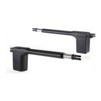
A OPERATOR
B OPENING PHOTOCELLS
C CLOSING PHOTOCELLS
D FLASHING LIGHT
E KEY SELECTOR SWITCH
F OPENING LIMIT STOP
G CENTRAL CLOSING STOP
H EXTERNAL CONTROL UNIT
3 PRODUCT TECHNICAL SPECIFICATIONS
ABACUS 220
ABACUS
220 ONE
ABACUS 220 ABACUS 300
ABACUS
300 ONE
ABACUS 500 ABACUS 500
ABACUS
500 ONE
ABACUS 500
Power supply 24V
230V
~
50Hz
24V
230V
~
50Hz
24V
230V
~
50Hz
Operator power supply 70 W 180 W 110 W 280 W 110 W 280 W
Current input 3 A 0,8 A 5 A 1,2 A 5 A 1,2 A
MAXIMUM THRUST 1500 N 1400 N 2000 N 1800 N 2000 N 1800 N
NOMINAL THRUST 500 N 400 N 600 N 700 N 600 N 700 N
Intermittenza di lavoro 30% 0,3 Intensive 0,4 Intensive 0,4
Grado di protezione IP 44 D
Classe di isolamento
II
1 earthing
II
1 earthing
II
1 earthing
Working temperature da -20°C a + 50°C
Peso max del cancello SEE THE CHART
Velocità a vuoto 15 mm/s 14 mm/s 22 mm/s 15 mm/s 22 mm/s 15 mm/s
Weight 8,2 Kg 8,6 Kg 11,2 Kg 11,6 Kg 11,9 Kg 12,3 Kg
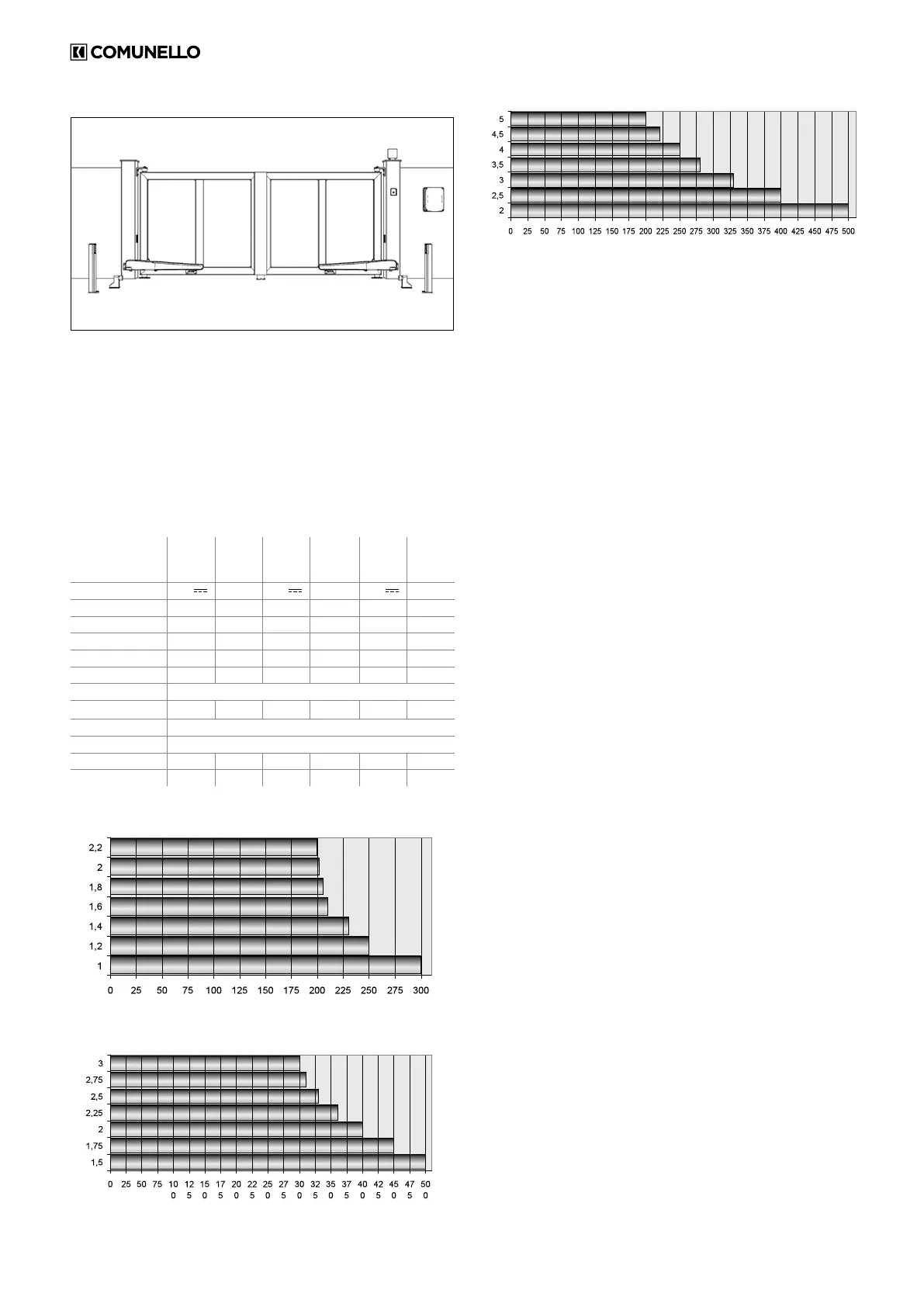
LEAF WEIGHT (Kg)
LEAF LENGHT (m)
LIMITS OF USE - ABACUS 220
LEAF WEIGHT (Kg)
LEAF LENGHT (m)
LIMITS OF USE - ABACUS 300
LEAF WEIGHT (Kg)
LEAF LENGHT (m)
LIMITS OF USE - ABACUS 500
4 INSTALLATION
4.1 PRELIMINARY CHECKS
Before starting the installation work, check the condition of the product
components, the suitability of the chosen gate operator model and the
suitability of the intended installation environment:
• Ensure that all material used is in perfect condition and t for purpose.
• Make sure that the mechanical structure of the gate is suitable for
automation. This product cannot be used to automate a gate unless the
gate is already in good working order and safe; furthermore, it cannot
remedy defects caused by incorrect installation or lack of maintenance
of the gate.
• Check that the operating conditions of the devices are compatible with
the stated operating limits.
• Move the gate leaves manually in both directions to ensure the force
required is constant throughout the full range of movement.
• Move the gate leaves manually to any position then release them to
check that they remain stationary.
• Check that the area in which the operator is to be mounted is compatible
with the size of the unit and make sure there is sufcient clearance for
the full movement of the arm.
• Ensure that there is sufcient space around the operator to perform the
manual release procedure.
• Ensure that the surfaces on which the devices are to be mounted are
solid and able to provide a secure anchorage.
• Ensure that all devices to be installed are in a sheltered location and
such as to minimize the risk of accidental impact.
4.2 OPERATING LIMITS
Before starting the installation work make sure the operator is correctly sized
in relation to the dimensions and length of the gate leaves and within the
limits of the values given in the chapter “Product technical specications”.
4.3 PREPARATORY WORK FOR INSTALLATION
With reference to gures 1A and 1B, choose the approximate position in
which each component of the system is to be installed and choose the
most appropriate connection layout. List of components required:
• Electromechanical operators
• Pair of photocells
• Pair of opening and closing limit stops
• Posts for photocells
• Flashing light
• Keyswitch or digital keypad
• Vertical electric lock for gate leaves of more than 3 m
• Control unit
4.4 INSTALLING THE ABACUS OPERATOR
4.4.1 INSTALLATION:
• Release the operator as shown in FIG. 2 and FIG. 3.
• Remove the rear cover as shown in FIG. 4.
• Perform the manual release as described in heading 4.4.3.
• Choose the position for the gate operator in correspondence with a
sturdy cross member on the gate.
• Secure plate Z1 to the gate pillar on a provisional basis, orienting it in
accordance with the width of the pillar (FIG. 5A).
• Cut and provisionally x the drilled plate (FIG. 5B) taking account of the
dimensions shown in FIG. 1A and FIG. 1B
• With the gate fully closed, provisionally x plate Z2 to the gate leaf. Weld
the drilled plate (FIG. 5C) observing the dimensions shown in FIG. 1A
and FIG. 1B.
• Couple the operator to the rear bracket using the supplied pin (FIG. 6).
 Loading...