Do you have a question about the CONCORD RM-08 and is the answer not in the manual?
Locate transmitter, receiver, and wall control. Align dip switches in all three units identically for system function.
Detach the existing switch housing and its internal components from the fan.
Choose the correct capacitor based on fan model and connect it to the receiver module.
Connect wires from the fan's Molex plug, light kit, and capacitor to the receiver module.
Connect the receiver's Molex plug to the fan's connector and secure the housing.
Mount the bracket to the ceiling junction box and connect fan/receiver wires to house wiring.
Hang the fan motor assembly onto the mounting bracket and install the ceiling canopy.
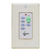
Turn off power, remove old switch, and install the new wall control unit in its place.
Learn to operate fan speed, direction, and light dimming using wall control and remote.
| Frequency Range | 433.92 MHz |
|---|---|
| Modulation | ASK |
| Operating Voltage | 12V DC |
| Input Voltage | 12V DC |
| Frequency | 433.92 MHz |