- 4 -
NOTE: If your fan has uplight or motor center band lighting you MUST connect the
WHITE Capacitor wire (marked “For Light”) to the BLUE
wire coming down from fan
(see figure 3B).
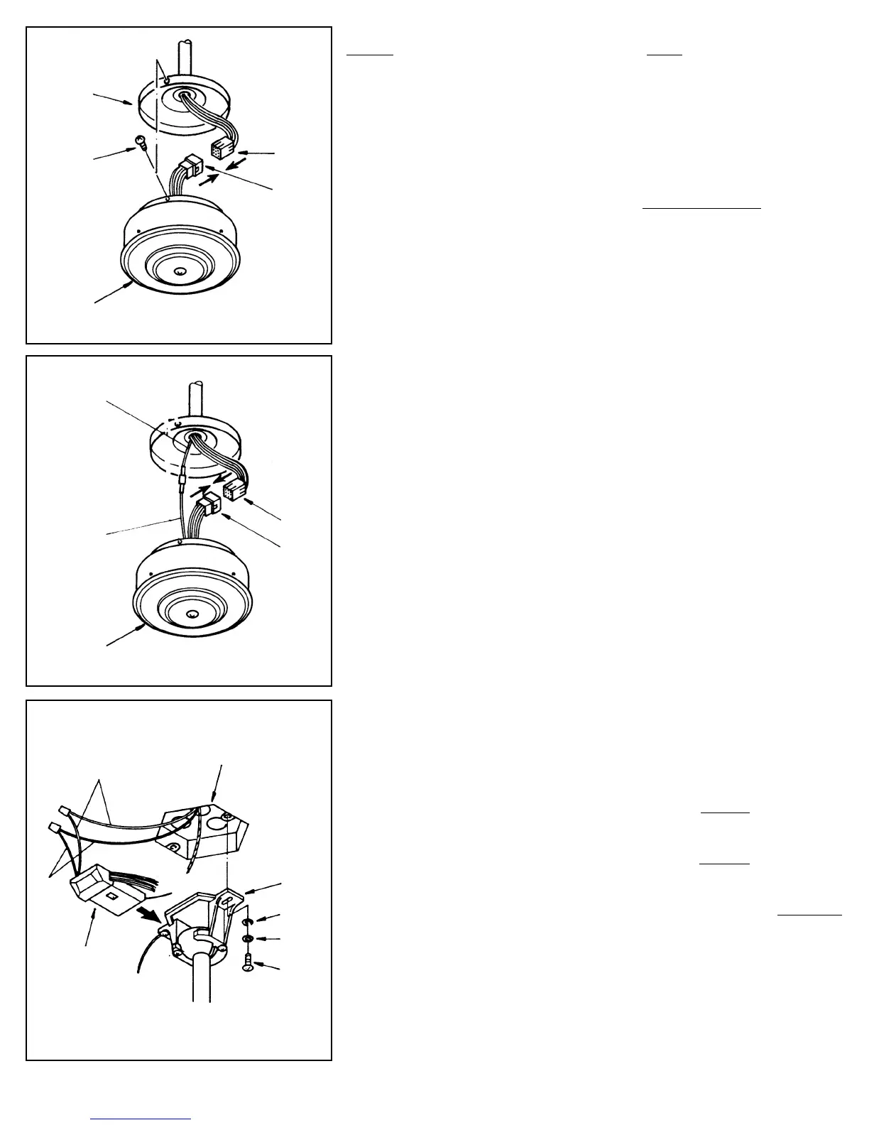
STEP 3
Connect the Molex plug from the switch housing unit to the end from the fan.
These plugs are notched and will connect in one direction only. Match the
colored sides and push together. The Switch Housing has 3 slotted holes
around the top. Align these holes with the three screws on the mounting plate.
Push the Switch Housing up and rotate to the right so the screws are at the far
left of the horizontal slot.
Tighten each screw (see figure 3A).
STEP 4: Install Mounting bracket
Loosen the two canopy mounting screws on the downside face of the mount-
ing bracket. Back them out about half way. This will allow for easier instal-
lation of the ceiling canopy later.
Install the mounting bracket onto the electrical junction box in the ceiling
using 2 machine screws, 2 washers and 2 lock washers (see figure 4). The
mounting bracket has slotted holes to enable it to move sideways for proper
alignment.
Make sure the mounting bracket is centered over the electrical junction box
and that it is securely attached.
NO MOVEMENT SHOULD OCCUR BETWEEN THE MOUNTING
BRACKET AND THE ELECTRICAL JUNCTION BOX.
Pull the electrical wires in the junction box down and through the mounting
bracket.
STEP 5 (see figure 4)
-Attach the WHITE wire from the junction box to the WHITE wire from the
receiving unit.
-Attach the BLACK wire from the junction box to the BLACK
wire from the
receiving unit.
-Now connect the GROUND wire from the mounting bracket to the GROUND
wire in the ceiling junction box.
NOTE: Make sure and use wires nuts on these connections. DO NOT USE
PLASTIC TAPE.
Molex
Switch
Housing
Molex
White
Black
Receiving
Unit
Junction Box
Mounting
Bracket
Washer
Washer
Screw
Figure 3A
Mounting
Plate
Molex
Screw (3)
Switch
Housing
Molex
Figure 3B
BLUE From
Uplight
WHITE Wire
marked “For Light”
Figure 4