10 Modbus RTU
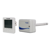
4.3 Connection and conguration of the Integrated Controller for Modbus RTU
3V
CR2032
GND + – GND + – GND + –24V GND
BMS
(USB)
RJ45
J7
J4J8J11
J6
J10
J12
J14
3J 2J
J7
J4
GND
+
–
Fig. 2: Integrated Controller (back view)
– Modbus RTU communication via port J6 "BMS"
– Jumper J7 has to be set for all devices.
– Jumper J4 only has to be set for the last devices in the net (end of line termination at the beginning
and end of the Modbus net). Jumper J4 set = end of line termination resistor activated.
– Jumper J4 has to be always removed by using the optional galvanic isolation (see chapter 9).
– All devices have to connected via GND.
– Software Version 1.1.0.23 or higher is needed (recommended software version 5.x.x.x or higher).
Important: When laying the network cabling,
make sure there is sufcient distance to other
cables, especially if they are connected to the
mains!
 Loading...