Calibration 11
NOTES:
1. If reading is in motion or correction required is not within ±0.8% of full-scale, no entry is made.
2. If entry is valid, the display momentarily indicates the correction value (in percent) and the memory location at
which it is stored.
3. If 100% ±0.05% is not obtained, repeat the zero/span calibration sequence.
4. Absolute only unit: Maximum vacuum standard display reading of 0.04 PSIA.
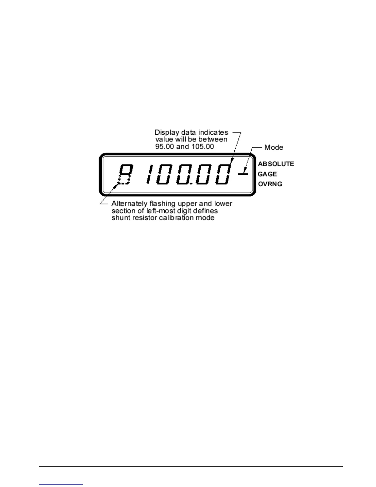
3.5 Shunt Resistor Calibration
To place the UPC5000/5010 into shunt calibration mode, install the Condec Calibration Module (PN 60109) and
select the SHUNT MODE position of the rotary switch. The display is shown in Figure 3-4.
Figure 3-4. Display in Shunt Resistor Calibration Mode.
With the UPC5000/UPC5010’s highest pressure range selected, perform the four step sequence described below.
1. Gage Only and Absolute/Gage Units: be sure the input pressure is set at 0 PSIG.
NOTE: Absolute Only Units: Must use a vacuum pump with PSIA display, to reach as close to 0 PSIA as possible
(maximum vacuum standard display reading of 0.04 PSIA).
2. Press and hold the ZERO button on the module until a stable zero indication is obtained.
3. Release the
ZERO button and allow the display to stabilize at its shunt resistor calibration number (100 ±
5.00%).
4. Press the
ENTER button on the module. When accepted, the bottom half of all display digits
momentarily illuminate.
3.6 Voltage/Current Input Calibration
To calibrate a current generator capable of generating 20 mA, it should be connected to the COMMON and
CURRENT INPUT jacks (Figure 2-2 on page 4 [14]). The DISPLAY SELECT switch (16) should be in the
VOLTAGE position.
1. Set the Condec Calibration Module (PN 60109) to the
ZERO/SPAN position (see Figure 3-2 on page 9 for
display reading).
2. Press the
ENTER button on the module. The display reads 0.00.
3. Set the current generator for 20 mA output. Press the
ENTER button on the module. The display should
read 100.000.
4. Turn the
DISPLAY SELECT switch (16) to the CURRENT position. Display will read 20.000.
5. Disconnect the current generator.
NOTE: If the display reading is off, set the Current Generator to 0, and press the ENTER button on the Condec
Calibration Module. Set the Current Generator for 20 mA output. The display will read 20.000. If the display reading is
off, press the ENTER button on the module. If the display reading is not 20.000, CPU is faulty and requires servicing.