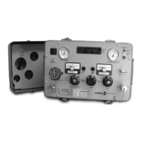
14 UPC5000/UPC5010 Operation & Maintenance Manual
4.0 Maintenance and Service
This section outlines the mechanical and basic electrical repair procedures for the UPC5000/UPC5010.
4.1 Troubleshooting
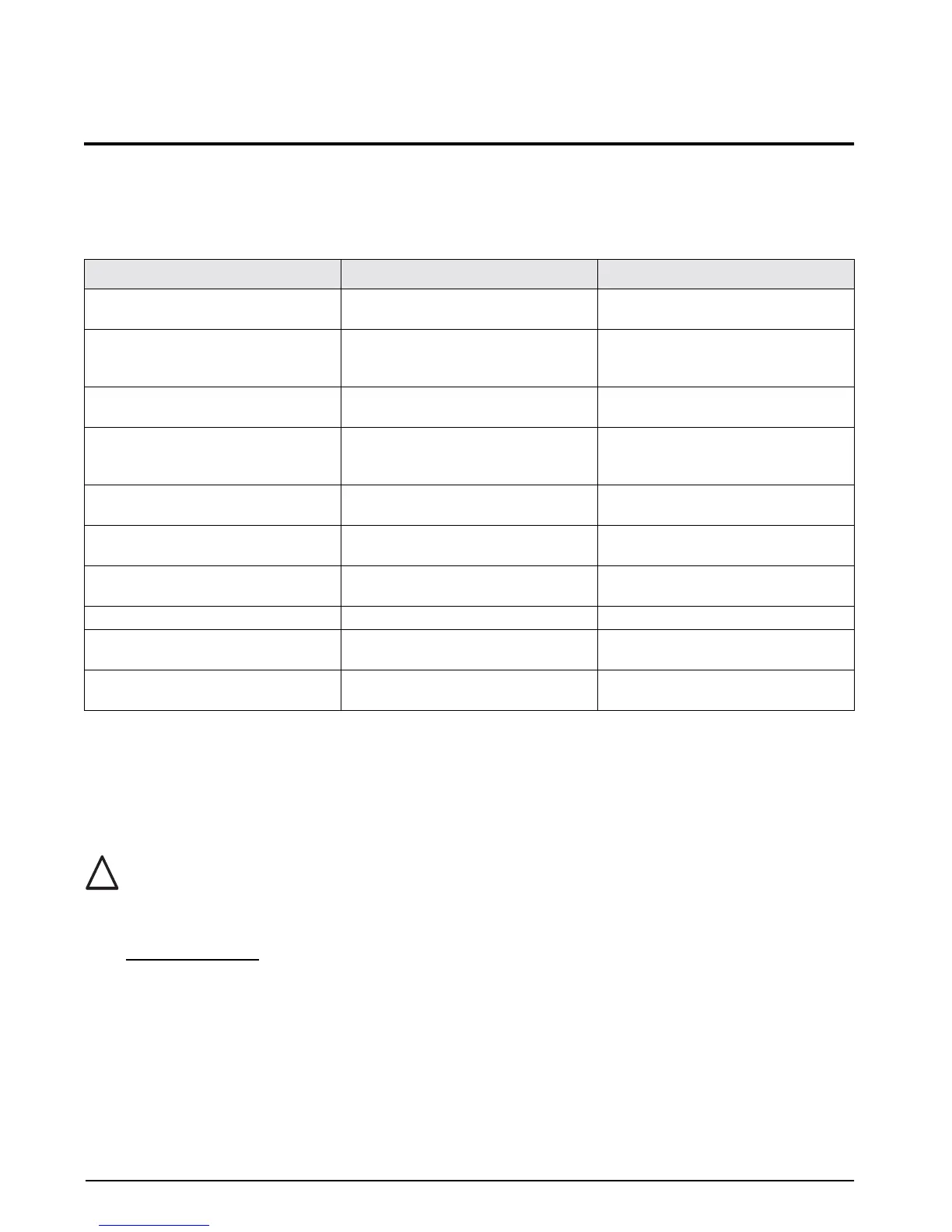
Use Table 4-1 below for information on troubleshooting the UPC5000/UPC5010.
4.2 Maintenance and Service Procedures
The repair procedures cover the major components and sub-assemblies which are critical to the proper
functioning of the calibrators and that need periodic maintenance over the life of the unit. Although some
mechanical sub-assemblies could be replaced without venting cylinder it is not recommended.
Only those persons who are formally trained as skilled technicians should attempt to repair these units.
All safety precautions should be observed due to the presence of electrical components and
high-pressure cylinders. Unit must always be unplugged from power source.
4.2.1 Panel/Chassis Removal and Installation
UPC5000 Removal
Tools required: Phillips screwdriver
1. Loosen and remove the eight screws (PN 14862) that secure the panel assembly to the enclosure.
2. Lift the panel and chassis by grasping the regulator knob and test port and grasping under the panel
edges. Ensure that the wire harnesses do not catch and snag.
3. Gently set the panel/chassis assembly on a bench top. It can be rested on the panel bottom and chassis
edge with the panel tilted at an angle from its vertical.
Symptom Problem Remedy
No lit display Unit will not energize Check fuse, check power source, check
power switch
Display slowly decreases over time Leak in system Check all compression and pipe fittings
with snoop, bottle of liquid leak gas
detector (PN 64781)
Display does not respond when Vernier
knob is turned
No Vernier control Readjust isolation valves on Orion;
replace O-ring on Vernier piston
Display increases or decreases when
COARSE (Pressure) or VENT valves are
closed
No Pressure or Vent control Replace valve seats or O-rings in valves;
check valve needles
Unit will not stay in CAL; display shows
"o" and reads a high value at zero PSIG.
Transducer over-pressurized Replace transducer
Low battery indicator on display
illuminates when unit is powered
Low or no battery power Re-charge battery, check power supply
charging voltage
No display when in battery mode after
charging
Battery will not hold charge Replace battery
Display will not zero Display will not zero Perform a ZERO/SPAN calibration
Display shifts Transducer drifts or possible over
pressure
Replace transducer
Gas escapes when external supply
pressure is bled
Nitrogen cylinder will not remain charged Remove inlet check valve; clean or
replace
Table 4-1. UPC5000/UPC5010 Troubleshooting
!
Caution