22
Appendix
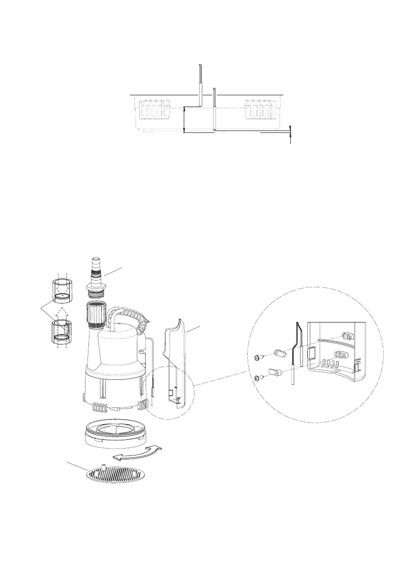
290 mm
175 mm
51.5 mm
157 mm
1
2
3
4
1 mm
20 mm
A
B
Figure 3
Figure 4
Moisture sensor switching levels
A = On sensor, B = Off sensor
Assembly illustration
1. Hose adaptor
2. Non-return valve
3. Sensor cover
4. Inlet screen
Attention:
Take care if separating the sensors from
the cover immediately after the pump is
switched off as they become hot when
in use (approx 60 °C).
GC-P-FLOW-F-12-1101-JH1.indd 22 24.01.12 09:52