C o n e r g y IP G s t r in g in v e r t e r s e r ie s Instruc tio n m anual 15
3 Pro d u c t d e s c r ip t io n
ENGLISH
AC disconnect (5) It must be possible to disconnect the AC supply from the grid
(on the AC side) by means of a disconnector. This is a
prerequisite for ensuring the absence of current to the unit,
e.g. during maintenance work. The disconnection device
must be secured against being switched back on.
Integration with the grid
(6)
For power feed to the grid, connect the inverter to the low-
voltage mains.
For systems with AC output up to 4.6 kW, a single inverter is
generally used. For the operation of systems with higher
outputs, several string inverters are used and connected in
several phases.
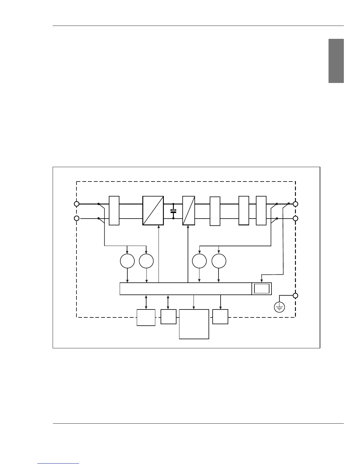
3.2 Block diagram
Fig. 3-2: Schematic block diagram
The electrical energy of the solar power system is conducted
via a sheathed filter. The filter prevents the penetration of
high-frequency line-bound interference. Varistors act as
surge voltage protection. The downstream switching of the
+
-
L1
N
PE
U
DC
I
AC
U
AC
Digital Monitoring
Display
I
DC
Phase
Shifting
EMC filter
LC filter
WR
BMT
Filter surge voltage
protection
CAN
In/Out
LED
CTRL
=
=
=
~
Grid protector