OPERATING & INSTALLATION INSTRUCTION 2-POST-LIFT
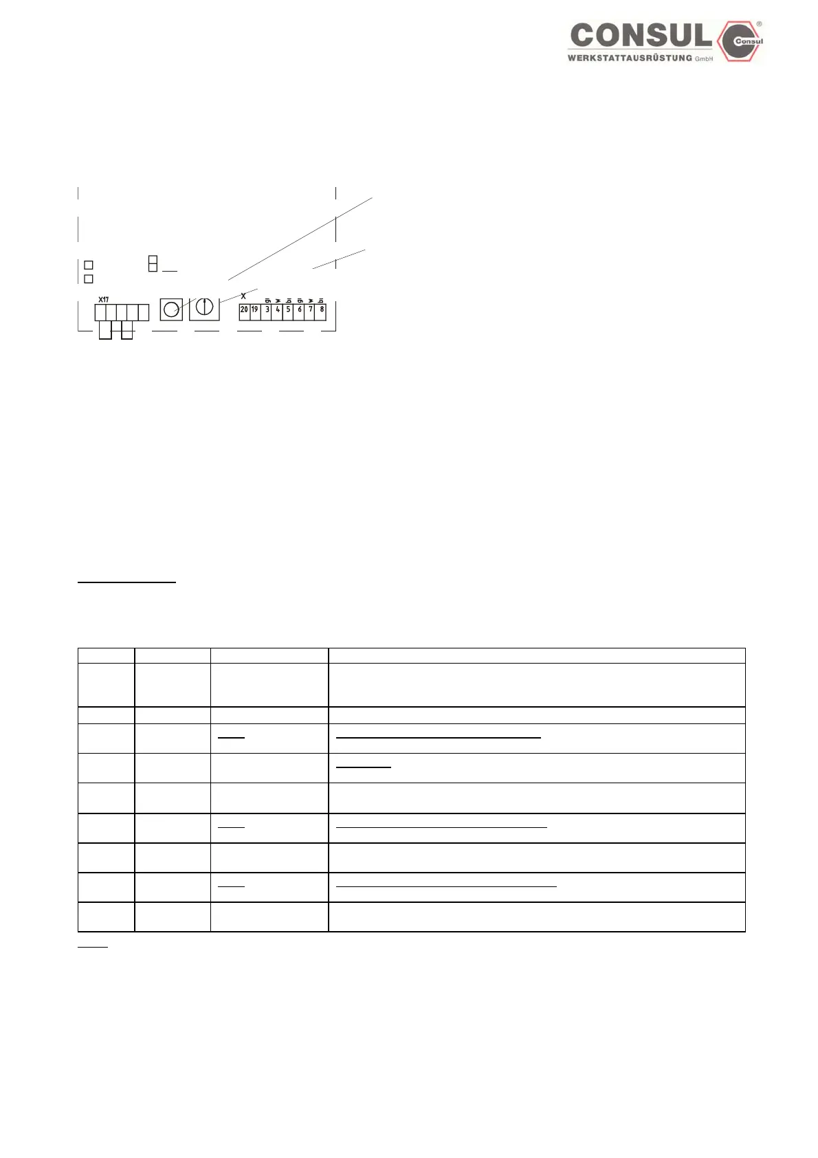
Switches on the main board for 1 motor-lifts
Switch on the electronic platine for initial installations and programmation
SGMX 2
LED Motor 2
LED Motor 1
Brücken
genicht
stecker
brückt
Enter
Ta s t e
Codie
Schalt
r-
er
Enter-button
Code switch
(turn with a small screwdriver)
ot
plugged
Code
switch
Enter
button
Green
White
Brown
Green
White
brown
Switch position: Function
0 Normal drive mode
1 Lower limit of carriage
(not active)
3 Upper limit of carriage
4 carriage position drive
5 (not active)
6 Safety Stopp and acoustic signal for further lowering of carriage
7* Potentiometer test mode
8* Connection, signal and EEPROM test mode
9* Fault test mode (not active)
*If you encounter any fault during these test modes, this fault will be stored on the EEPROM. The main board cannot be adjusted to
normal mode in this case. If normal drive mode is selected, and a fault acccurs during test mode, both red and green LED’s blink. To
overcame this situation, change defective parts or run test mode again.
New driving mode:
Switch on the main board – programming (initial installation of the potentiometer already done)
Step Switch Enter button: Fonction:
A 4 push Oparate mode
Lower the carriage til approx. 10mm over the ground and 10 mm overrun
reserve
B 5
Not active
C 1 push
push
Set lower limit after success of step A
Save mode
D 2
Not active
Save mode
E 0 push Normal operation mode (both LED are red)
Move both carriages til a height of max. 1900 mm - evt. lower
F 3 push
push
Set upper limit after success of step E.
Save mode
G 0 push Normal operation mode (both LED are red)
Lower lift to min. 200 mm above the ground in order to set safety stop.
H 6 push
push
Set safety Stopp after success of step G
Save mode
I 0 push Normal operation mode (both LED are red)
Programming finished
push = both LED are green. should be the above disconnection point not reached,
push = both LEDare blinking green. Continue in individual drive with position 4.
Attention: no end stops!
Page 48