OPERATING & INSTALLATION INSTRUCTION 2-POST-LIFT
Important notice:
If you encounter big differences in voltage or any other problems, it might happen that the main board is shut
down automatically for safety purpose. In this case the lift cannot be operated. To make it work again, this
can be done usually by turning the main switch on and off again.
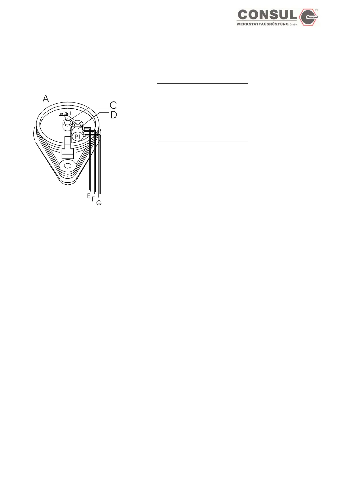
Top view main column:
A: main column
C: gear screw
D: Potentiometer
E: geen
F: brown
G: white
The path pick-ups P1 and P2 are not marked on the lift. The configuration of the components corresponds to this drawing. The
wiring of the path pick-ups must be carried out according to the colour scheme of the prescribed plan. Incorrect wiring upsets
the path pick-ups!
How to active the EEPROM
I. Main switch off
II. Jumper on both plugs
III. Main switch on
IV. Jumper on one plug or put it away until end of this process
V. Main switch off
VI. Main switch on
VII. The control is actived by turning the code switch to 8 and pushing the Enter button
Test connections, signal and EEPROM (Saving)
(Carriages are not near the end stops)
I. Turn switch to code 8.
II. Push ENTER button
III. LED 2 is blinking (green), the signal is on.
IV. Turn the „up“ switch until the carriages start to move up.
V. The lift will move a short distance upwards.
VI. LED 1 is blinking (green), the signal is on.
VII. Turn the „down“ switch until the carriages start to move down.
VIII. The lift will move a short distance downwards.
IX. If the test has been successfull, both LED are blinking green.
X. If any fault accured, both LED are blinking red.
XI. Push ENTER button (EEPROM-Test)
XII. If everything is ok, both LED are green.
XIII. If the electronic encounters have any problems, both LED are blinking red, the signal is on. To rectify the fault, the lift has to be
turned off. The jumper on the main board has to be put onto both connections, turn main switch on. After that turn off main switch
again, put the jumper onto one connection only and turn main switch on again.
XIV. Set code switch to any mode.
XV. Push ENTER
Page 49