EMA‐90N UserManual IM128‐Uv0.74 Pag.4/32
Installation
Warning for the user
Read carefully the instructions/indications contained in this manual before installing and using the instrument.
The instrument described in this manual is intended for use by properly trained staff only.
Safety
This device has been manufactured and tested in compliance with EN 61010-2 standards. In order to maintain these conditions and to ensure safe operation, it
need to comply with the indications and markings contained in the manual.
When the device is received, before beginning installation, check that it's O.K. And it has not suffered any damage during transport.
When starting installation make sure that the operating voltage and mains voltage are compatible with the device instructions. The device power supply must not
be earthed.
Maintenance and/or repair must be carried out only by qualified and authorized personnel. If there is ever the suspicious that, that there is a lack of safety,
during operation, the device must be disconnected and cautions taken against accidental use.
Operation is no longer safe when:
- The instrument doesn't work.
- The measured value has obviously wrong or unreasonable.
- There is visible damage.
- After serious damage incurred during transport.
- After a storage under unfavourable conditions.
During normal operation of the devices, hazardous voltages at its terminals and in particular on the terminals of voltage and current transformers connected and
on the terminals of the digital input and outputs.
The secondary circuits of the voltage and current transformers are capable of generating hazardous voltages and currents when their primary circuit is powered.
Follow the standard safety precautions when performing any installation or service (such as making sure that the power supply is disconnected, disconnecting
the fuses of the transformer voltages, short-circuiting the secondary of current transformers etc.).
Don’t use the instrument when failure may cause injury or death, or generate sufficient energy to cause a fire.
The instrument is equipped with a fuse on the power supply type: 5x20mm 1A 250V time lag.
Auxiliary power supply
The instrument can be supplied with a voltage independent by the monitoring line. In this case, the instrument continues to operate
independently by the voltage present on the lines under control.
Alternatively, only for 90÷250Vca/cc version, it is possible to take the power from the network under test, using the phase and neutral for a
4-wire network, phase to phase in a 3-wire system without neutral or from a VT in a MT application. In this case when the voltage of the
monitored line falls below the minimum limit, the instrument turns off.
Voltage Inputs
4 terminals are available for direct connection to 3 phase network with neutral. In case of a 3 phases balanced system without neutral, or
not distributed neutral to leave terminal N free.
3 inputs, range 30 ÷ 400Vac phase to neutral - 52 to 693Vac phase to phase (see Technical Features table for details); over these values
must used the external voltage transformers.
Frequency range: 50/60Hz.
Permanent overvoltage allowed: 480Vac phase to neutral - 830VAC phase-phase.
Overvoltage category: II (permanent installations).
Pollution degree: 2 (normally non-conductive, conductive condensation temporary).
Input resistance: > 1.8MΩ.
Load (Burden) for each voltage input: 0.09VA.
Note: To detect the frequency of the network the terminal VL1 must be always connected.
Current Inputs
Current measurements can be performed by connecting the terminals of Current inputs.
All current inputs are isolated by current transformers with different ranges depending on the model of the instrument.
They can be interfaced directly to the line to be monitored or to be connected to the output of external CT with higher range.
The connections to the lines to be monitored are described in chapter “Wiring diagrams”.
With neutral current input option installed, the instrument allows the direct measurement of neutral current in the same way described for
the line inputs.
Note: it is essential to observe the correct phase sequence, not invert the connections between the phases of the current inputs
and voltage (i.e. the CT placed on L1 phase must absolutely match at I1 Current and VL1 voltage). Do not invert the terminals S1
and S2 of the CT because the measurement of power factors, and the powers would no longer be trusted.
Neutral Current: the nominal current range depends by the version.
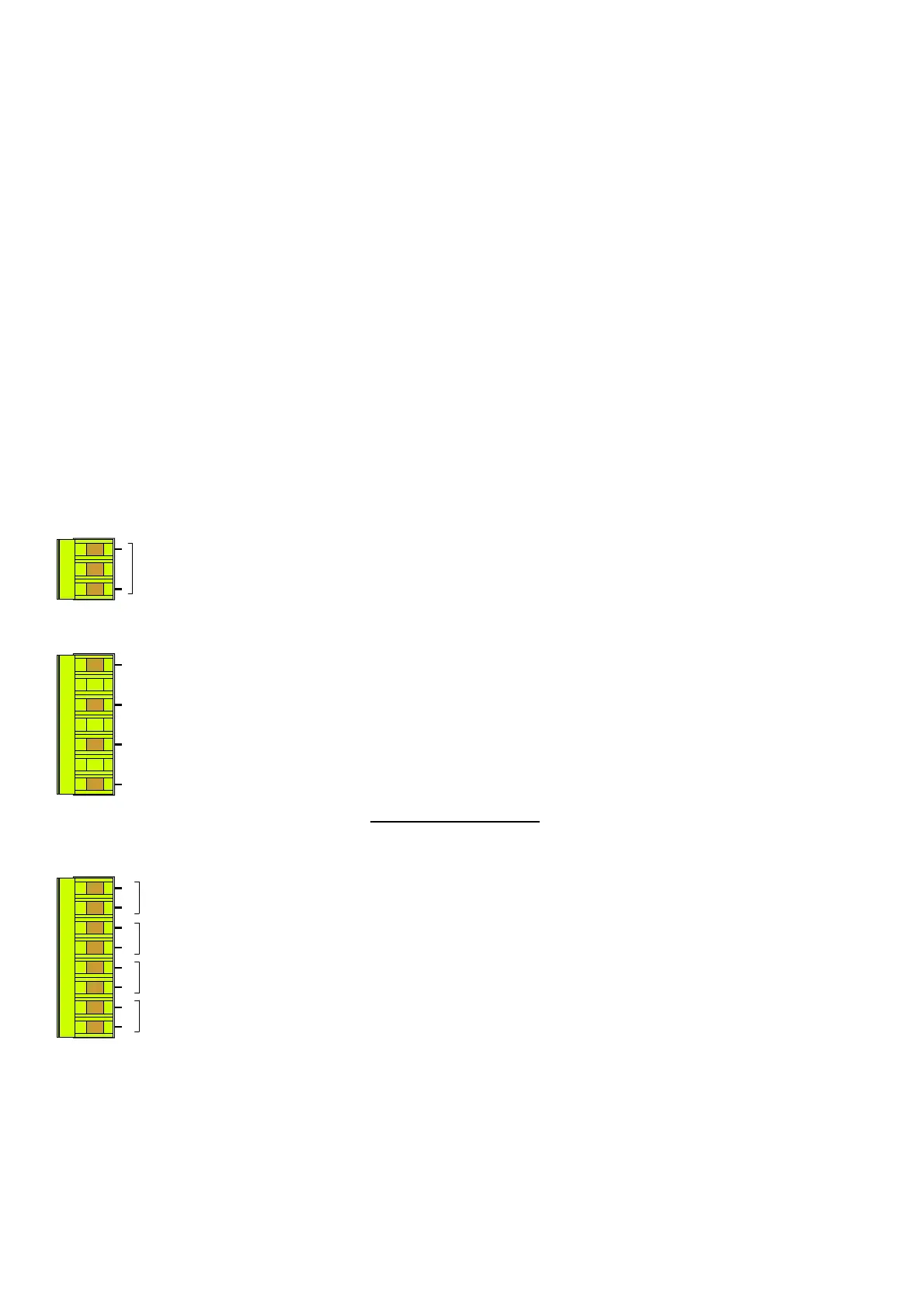
1
2
AUX
S2
S1
S2
S1
S2
S1
S2
S1
In
I3
I1
I2
N
VL3
VL2
VL1


 To Next Page
 Loading...