3
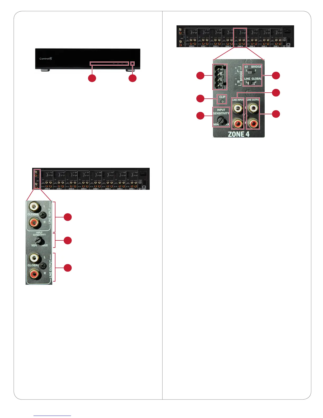
Back Panel: Zone I/O
A Input Phoenix connector.
B CLIP indicator—When clipping (caused by overly
strong signal or gain) is detected, this lights red.
C INPUT SENSITIVITY (gain).
D Zone stereo and source selectors—While ST is
selected, inputs and outputs process L and R
channels separately. While BRIDGE is selected,
the zone amplifies only the L channel (R channel
is disabled). With LINE selected, the source for
the zone is the source connected to the zone’s
LINE INPUT jacks. With GLOBAL selected, the
source for the zone is the GLOBAL LINE INPUT
source.
E LINE INPUT L and R jacks.
F LINE OUTPUT L and R jacks.
A
B
C
D
E
F
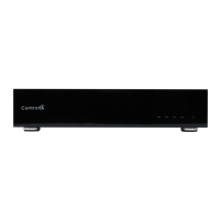
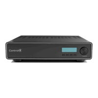
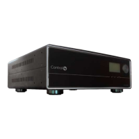
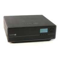
Front and Rear Panel
Front Panel
A Zone indicators (LED)—Displays only when zone
has an active audio input. Lights blue when
audio is being output, and lights red when signal
processing encounters a fault.
B Power indicator (LED)—Lights blue for on, and
red for standby.
For general information about the product, see the
Product pages at www.control4.com.
Back Panel: Global I/O
A Global line input
B Global line input sensitivity (gain)
C Global line output (unamplified, unaected by
gain)
A B
A
B
C
 Loading...