5
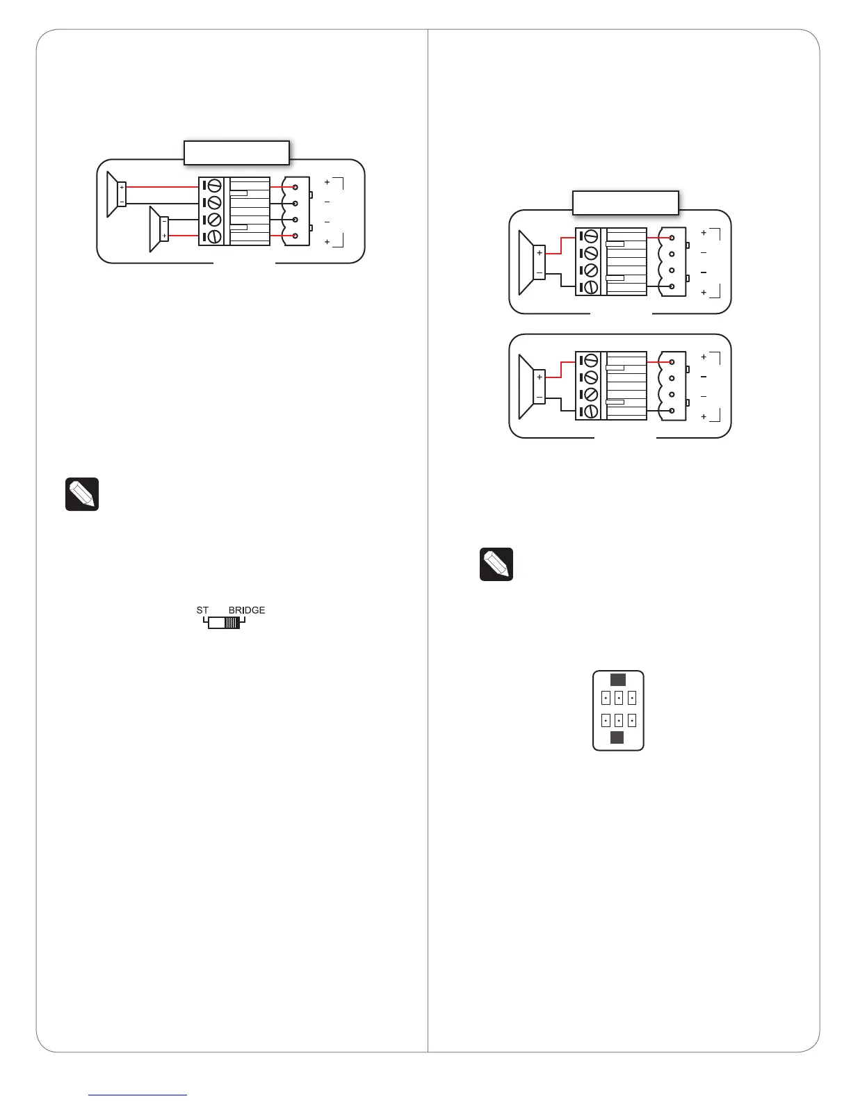
3 Connect the left speaker to the LINE OUTPUT
(L) jack, and the right speaker to the LINE
OUTPUT(R) jack. If you are using a Phoenix-style
connector, wire it as shown below.
Setting Up Bridge Mode
In Bridge mode, the R channel is disabled. This
eectively doubles the power output of the
remaining L channel, but at the cost of outputting
only a mono signal. To set up a stereo signal while
using Bridge mode, you will need to set up two (2)
separate zones:
NOTE: In Bridge mode, outputs are rated for
only eight (8) ohm loads and will not function
correctly for four (4) ohm loads.
1 In two (2) neighboring zones (for ease of
connections), called Zone A and Zone B in
this example, slide each ST/BRIDGE switch to
BRIDGE.
2 In Zone A’s port cluster, connect the audio
source’s L channel to the LINE INPUT (L) jack.
3 Also in Zone A’s port cluster, connect the speaker
for the L channel output to the LINE OUTPUT (L)
jack. You must use the + signals of the Phoenix-
style connector. Make sure to note speaker
polarity. You should connect the positive speaker
polarity to the top + and the negative speaker
polarity to the bottom +.
BRIDGE
L
R
Zone
Stereo Mode
L
R
4 In Zone B’s port cluster, connect the audio
source’s R channel to the LINE INPUT (L) jack.
Again, you must use the + signals of the Phoenix-
style connector. Make sure to note speaker
polarity. You should connect the positive speaker
polarity to the top + and the negative speaker
polarity to the bottom +.
5 Also in Zone B’s port cluster, connect the speaker
for the R channel output to the LINE OUTPUT (L)
jack.
NOTE: Phoenix-style connectors, if used in
Bridge mode, need to be wired identically
(left channel, identical polarity wiring) for
each zone.
Setting Up Trigger Mode
Trigger input/output controls:
When Trigger is ON:
• - NC = No connection.
• - OUT = Trigger Output. Driven High when
device is NOT in standby mode.
• - GND = Ground connection.
• - +5 = Constant +5V output.
• - IN = Trigger input. When Low, device will be
forced into standby; when High, device will
be forced to ON.
• - GND = Ground connection.
BRIDGE
L
R
L
Zone A
BRIDGE
L
R
R
Zone B
Bridge Mode
NC OUT GND
IN+5 GND
 Loading...