Home Controller
HC-300
Installation Guide
Supported Model
C4-HC300C-E-B Home Controller HC-300
Accessories Available for Purchase
What’s in the Box
The following are included in your Home Controller box:
• Home Controller HC-300
• Pluggable terminal block connector (1)
• System Remote Control with LCD Navigator display and 4 AAA batteries
• IEC 320 power cord
• IR emitters (6)
• HomeControllerHC-300InstallationGuide (this document). Note:Youcanndthis
and other related documents online at http://www.control4.com.
Introduction
WARNING! To reduce the risk of electrical shock, do not expose this apparatus
to rain or moisture.
AVERTISSEMENT! Pour réduire le risque de choc électrique, n’exposez pas cet
appareil à la pluie ou à l’humidité.
WARNUNG! Um das Risiko des elektrischen Schlages zu verringern, setzen Sie
diesen Apparat nicht Regen oder Feuchtigkeit aus.
The Control4® Home Controller HC-300 provides options for controlling lights, home
theaters, distributed audio systems, distributed video systems, and other devices controlled
using various protocols, such as Infra Red (IR) Serial, Contact, and Relay. It provides
extensive media management services for audio and video sources, such as CDs and DVDs
stored in connected devices. It also allows you to use an external storage device with USB
support for media storage, and it has multi-zone audio capabilities, sending music to rooms
throughout the home.
WhentheControllerandothersystemcomponentsareinstalledandcongured(using
Control4 Composer software or another Control4 setup program), your users can control
the system using one of the two (2) user interfaces included with this Cotnroller: On-Screen
Navigator or a System Remote Control or any other Control4 user interface device (sold
separately.
Ensure that your home network is in place before starting your system setup:
The Home Controller HC-300 requires a network connection (wired or WiFi) to use all
features as designed. When connected, the Home Controller can access web-based
media databases and Control4® system updates.
If mounting directly to a wall:
a. Obtain the HC-300 Wall Template, part # 851-00001, available at:
http://www.control4.com/dealer/support/pid.htm.
b, Attach the template to the wall with tape, then level it.
c. Screw or nail four (4) screws or nails into the wall where indicated.
d. Remove the template from the wall.
e. Pull to remove rubber strips from the feet of the HC-300 to expose the prepared
holes (no need to remove the existing screws).
f. Hang the HC-300 on the wall.
Connect the HC-300 controller to the network: To connect using an Ethernet connec-
tion, plug the data cable from the home network connection into the Home Controller
RJ-45 port (labeled “Ethernet”) and the network port on the wall or at the network switch.
Note: To connect using the optional USB WiFi adapter (C4-NWA-11G-USB), refer to the
installation instructions shipped with the adapter.
Only use the power supply included in this box.
Power up the controller: Plug the HC-300 power cord (provided) into the Home Con-
troller power plug port and an electrical outlet.
Note: The HC-300 may take several minutes to boot up and become operational.
Pleaseallowsufcienttimeforboot-up.
Connect system devices: As described in the “Connect Devices” section that follows.
Set up external storage devices as described in “Set up External Storage Device.”
1.
2.
3.
4.
5.
6.
Install the HC-300
• USB WiFi Adapter (C4-NWA-11G-USB)
Important Safety Instructions
1. Read and keep these instructions.
2. Heed all warnings and follow all instructions for this product in this and other Con-
trol4® documents included with or related to this product.
3. Improper use of this product may result in potential electric shock.
4. Do not use this product near water.
5. Never spill liquid of any kind on this product.
6. Clean this product only with a damp or dry cloth. Do not use liquid cleaners or aerosol
cleaners to clean the product.
7. Install this product according to the manufacturer’s instructions.
8. Install this product according to the National Electrical Code ANSI/NFPA 70 and the
prevailing local codes and requirements.
9. This product should be operated with the type of power indicated on the marked label.
If you are not sure of the type of power available, consult your Control4 dealer or local
power company.
10. Slots and openings on a cabinet rack, and components used with this product are pro-
vided for ventilation, reliable operation, and protection from overheating of the product.
These slots and openings must not be blocked or covered.
11. This product should never be placed near or over a radiator or heat register, or in a
built-in installation unless proper ventilation is provided.
12. Never push objects of any kind into this product through cabinet slots because they
maytouchdangerousvoltagepointsorshortoutpartsthatcouldresultinareor
electric shock.
13. Only use the attachments and accessories included with this product or recommended
by Control4.
14. Do not allow anything to rest on the power cord. Do not install or place this product
where people will walk on the cord.
15. Do not use extension cords with any products in a Control4 system.
16. If applicable, unplug this product during lightning storms or when unused for long
periods of time.
17. Donotexceedthemaximumwiresize(ifspecied)inthisguide.
18. Thisproductmustbeinstalledbyqualiedprofessionalsonly.
19. Do not attempt to service this product yourself except as noted in this guide. Opening
or removing covers of internal components may expose you to dangerous voltage
points or other risks.
20. Referallservicingtoqualiedservicepersonnel.Servicingisrequiredwhentheap-
paratus has been damaged or frayed in any way; for example, a power-supply cord or
plug is damaged, liquid has been spilled or objects have fallen into this product, this
product has been exposed to rain or moisture, this product does not operate normally,
or this product has been dropped.
Control4 Supported Devices
Control4 devices that communicate with this Controller include:
• Touch Screens—All types and sizes (such as portable, tabletop, and in-wall, or 10”, 7”,
5”, and mini)
• LCD Keypads
• Wireless 2, 3, & 6 Button Keypads
• Wireless Thermostats
• Speaker Points®
• Audio Matrix Switch
• MultiChannelAmpliers
• 4-ZoneAmpliers
• Multi Tuners (V1 or V2)
• Wireless Dimmers
• Wireless Switches
• Wireless Outlet Dimmers
• Wireless Outlet Switches
• Third-party devices
For a more information, refer to the Product pages at http://www.control4.com.
Requirements and Specifications
Prior to installing this product, ensure that: Ethernet network wiring is in place.
TheHomeControllerHC-300Cspecicationsare:
Model Number C4-HC300C-E-B
Network Support Ethernet—required
WiFi--optional, requires a WiFi adapter (sold
separately)
Media Recognition Online CD/DVD recognition and media information
service
Audio Playback Formats MP3: 32kbps to 320kbps, CBR and VBR
Display LED indicators
Power Requirements 100-240 VAC, 60/50 Hz, 0.26 A MAX
Dimensions H x W x D: 2.80” (71 mm) x 11.98” (304 mm) x 7.24”
(184 mm) (with feet and connectors)
Weight 4.7 pounds
Additional Resources
The following resources are available to provide you with additional support.
• HC-300 Wall Template, part # 851-00001, available at: http://www.control4.com/dealer/
support/pid.htm
• Your Control4 Reseller
• Control4 Web Site: http://www.control4.com
• Composer online help
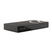
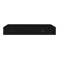
Front View
1. WiFi LED—ThisLEDblinksrstred,thenorange,andnallyblueduringtheboot
process. Once the operating system is running, the WiFi driver changes the LED color
depending on the signal strength of its connection to its associated access point.
Colors and signal strength are as follows: orange=Fair to Good, blue=Excellent, and
no light=No connection.
2. Data LED—This blue LED indicates streaming audio is received.
3. Link LED—BlueLEDlightindicatesHomeControllerhasbeenidentiedinaControl4
Composer project.
4. Power LED—Blue LED light indicates AC power is present. It turns on immediately
after the power is applied to the device.
5. IR Window / IR Blaster—For capturing third-party IR codes from hand-held devices
(such as remote controls) or blasting IR codes.
1
2 3 4
5
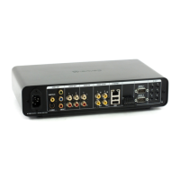
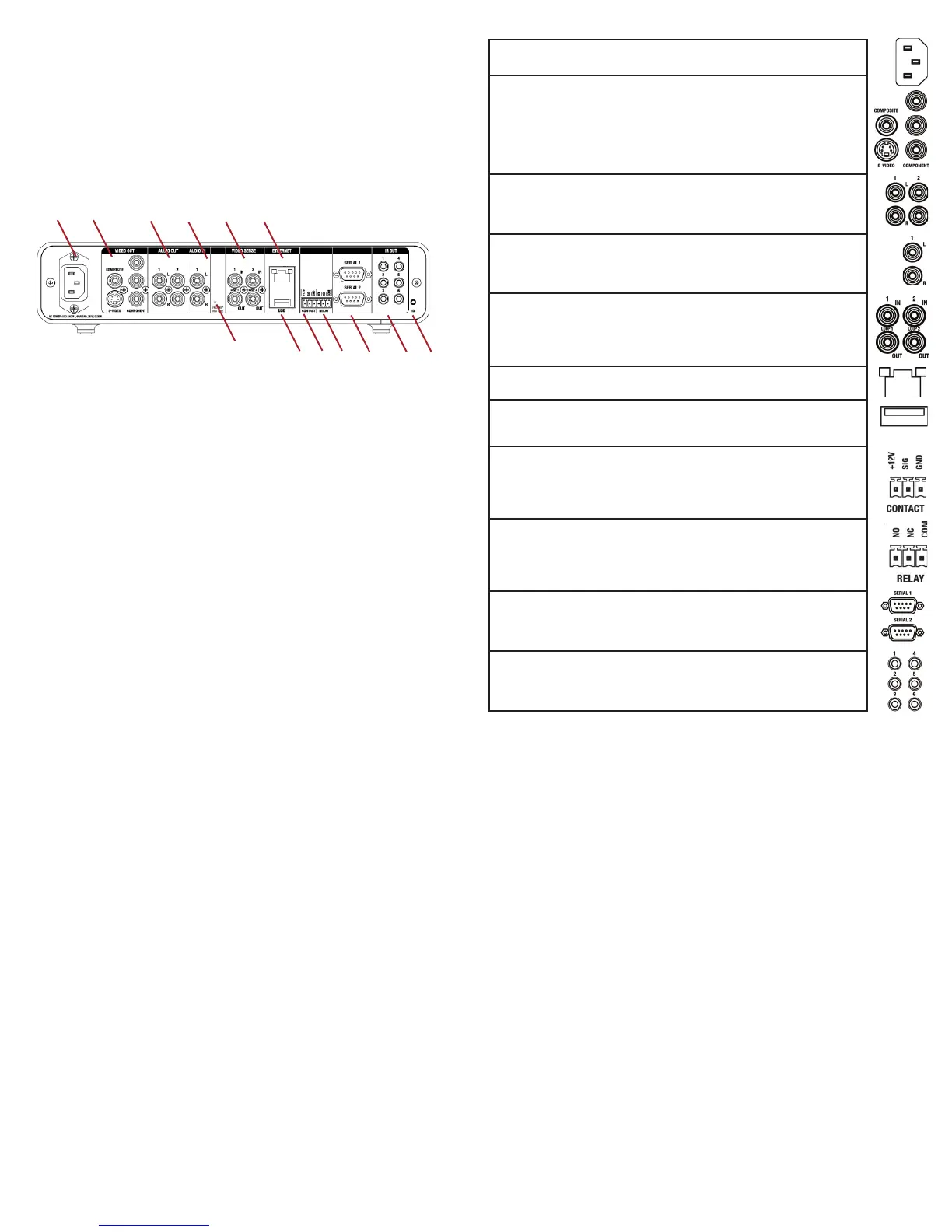
Back View
1. Power plug port—AC power receptacle for an IEC 320 power cord.
2. Video Out—Composite RCA, S-VIDEO mini-DIN, and Component RCA jacks.
3. Audio Out (2 Left-Right pairs)—RCA jacks for stereo channel line output (line level)
forampliersoraudioswitches.
4. Audio In (1 Left-Right pair)—RCA jacks for stereo channel input (line level) for one
stereo analog source.
5. Video Sense In-Out (2 pairs)—Composite In-Out RCA jack pairs for monitoring the
On/Off status of up to two (2) video sources.
6. Ethernet—RJ-45 jack for a 10/100 BaseT Ethernet connection.
7. Factory Restore Button—Restores the Controller to the factory defaults.
8. USB (1 port)—For external storage device with USB support (such as FAT32-format-
ted devices) and WiFi adapter (C4-NWA-11G-USB).
9. Contact (1 set)—Pluggable terminal block connector for one dry contact closure, logic
input connection, door contact sensor, or motion sensor.
10. Relay (1 set)—Pluggable terminal block connector for one (1) normally closed or
normally opened switchable connection.
11. Serial (2 sets, DB9)—Two (2) serial devices, such as a receiver or disc changer.
12. IR Out (6)—3.5 mm jacks for up to six (6) IR output transmitters.
13. Identication button—Easily-pressed button used when identifying this device in
Composer.
To install this Controller:
Connect Devices
Note: You can use the Composer software to step through the connection process before or
after the physical connections are completed.
Connect all applicable devices to the Home Controller HC-300 using one of the connection
options described in the following table.
Table 1. Connections Options
Power plug port—For use with the IEC 320 power connector (provided).
Video Out Options—Composite, Component, or S-Video port for display-
ing navigation menus on a monitor or TV. The Component jack is only for
displayinghigh-denitionvideo.Todisplaystandarddenitionvideo,use
the Composite or S-Video ports. When available, use S-Video instead of
Composite for a higher quality display.
Audio Out (2 Left-Right pairs)—RCA jacks for stereo channel line output
(linelevel)forampliersoraudioswitches.
Audio In (1 Left-Right pair)—RCA jacks for stereo channel input (line
level) for one stereo analog source.
Video Sense In-Out (2 pairs)—Composite In-Out port pairs for monitoring
up to two (2) video In sources, such as DVD players or VCRs, that allow
the system to determine the On/Off status of devices. Each Out port allows
the signal to loop through the Controller and continue to its intended video
connection. See “Use Video Sense Loops” for information.
Ethernet—RJ-45 for a 10/100 BaseT Ethernet connection.
USB (1 port)—For external storage device with USB support (such as
FAT32-formatted devices). See “Set up External Storage Device” for infor-
mation or to connect the optional WiFi adapter C4-NWA-11G-USB.
Contact (1 set)—Pluggable terminal block connector for one (1) dry contact
closure, logic input connection, door contact sensor, or motion sensor.
Provides power for small devices (12V), signal input (SIG), and return path
(GND).
Relay (1 set)—Pluggable terminal block connector for one (1) normally
closed or normally opened switchable connection, such as a blind, a
replace,oraprojectorscreen.ThesetcontainsaconnectionforNormally
Opened (NO), Normally Closed (NC), and Common (COM).
Serial (2 sets)—DB9 connector for a serial device, such as a receiver or
disk changer. See “Connect the Serial Ports” for more information.
IR Out (6)—3.5 mm jacks for up to six (6) IR output transmitters.
See “Set Up IR Emitters or IR Blaster” for more information.
Use Video Sense Loops
Video sensing can enhance the ability to sense the power state of a device, such as
whether the device is “on” or “off.” To add video signal sensing capabilities for a video
device (such as a VCR, DVD player, etc.), connect one of the device’s composite Video Out
ports to a HC-300 Video Sense In port. Use the companion Video Sense Out port for the
device’s video out as needed. For Video Sense only (no loop-through), connect a device’s
Composite Video Out port to one of the two (2) Video Sense In ports.
Use Pluggable Terminal Block Connectors
For the Contact and Relay ports, the HC-300 makes use of a pluggable terminal block
connector—a removable plastic part that locks in individual wires, which is included.
To connect a device to the Pluggable Terminal Block:
1. Insert one of the wires required for your device into the appropriate opening in the
Pluggable Terminal Block you reserved for that device (refer to Figure 1 on page 2).
For example, if you were adding a motion sensor, you would connect its wires to the
following Contact openings: power input to +12V output signal to SIG, and ground
connector to GND. See the sections that follow for instructions about connecting the
various protocols.
2. Lower the openings latch until it locks the wire in place.
3. Repeat Steps 1-2 for all wires required for your device.
Note: When you connect dry contact closure devices, such as door switches, connect the
switch between +12V (Power) and SIG (Signal).
Connect to the Contact Port
The HC-300 provides one (1) contact port as a subset of the pluggable terminal block pro-
vided.Seethefollowinggurestodeterminehowtoconnectthedevicetoacontactport.
WARNING! This CLASS I apparatus must be connected to an AC mains socket
outlet that has a protective earthing connection (i.e., third-prong ground conduc-
tor). DO NOT DEFEAT THE PROTECTIVE EARTHING CONNECTION!
1
2 3 4
5 6
7
9 10
11 12 13
8
The following section provides more information about other connection options.
 Loading...